BBC Microbit
![]()


BBC micro:bit
IS31FL3731 LED Matrix Driver
Introduction
The electronics company, Adafruit, have a range of 16x9 charlieplexed LED matrices. There is also a driver board that you solder to the LED board. Together, you're paying around £13 for a really nifty i2c controlled charlieplexed matrix.
There is a slightly high pitched noise when the display has lots of lights at high PWM. That, according to Adafruit, is normal. For the 144 neatly arranged LEDs, you're not going to complain about a little whining, are you?
Circuit
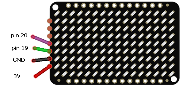
Your connections here are the basic i2c connections. The matrix is shown in the diagram, but the pins you are connecting to are on the driver board.
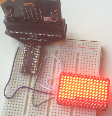
The following picture shows the display, on its driver board and connected to a micro:bit.
Programming
This code is adapted from the Adafruit libraries with this being based more on the approach used in the Arduino library for the main functions I got around to trying.
from microbit import *

class Matrix:
    ADDRESS = 0x74

    REG_CONFIG  = 0x00
    REG_CONFIG_PICTUREMODE = 0x00
    REG_CONFIG_AUTOPLAYMODE = 0x08
    REG_CONFIG_AUDIOPLAYMODE = 0x18

    CONF_PICTUREMODE = 0x00
    CONF_AUTOFRAMEMODE = 0x04
    CONF_AUDIOMODE = 0x08

    REG_PICTUREFRAME  = 0x01

    REG_SHUTDOWN = 0x0A
    REG_AUDIOSYNC = 0x06

    COMMANDREGISTER = 0xFD
    BANK_FUNCTIONREG = 0x0B

    FRAME = 0

    def __init__(self):
        # off an on again
        self.write_reg8(self.BANK_FUNCTIONREG, self.REG_SHUTDOWN,0x0)
        sleep(10)
        self.write_reg8(self.BANK_FUNCTIONREG, self.REG_SHUTDOWN,0x1)
        # select picture mode
        self.write_reg8(self.BANK_FUNCTIONREG, self.REG_CONFIG, self.REG_CONFIG_PICTUREMODE)
        self.write_reg8(self.BANK_FUNCTIONREG, self.REG_PICTUREFRAME, self.FRAME)
        self.fill(0)
        for f in range(8):
            for i in range(18):
                self.write_reg8(f,i,0xff)
        # turn off audio sync
        self.write_reg8(self.BANK_FUNCTIONREG,self.REG_AUDIOSYNC, 0x0)


    def fill(self, value):
        self.select_bank(self.FRAME)
        for i in range(6):
            d = bytearray([0x24 + i * 24]) + bytearray(([value]*24))
            i2c.write(self.ADDRESS, d, repeat=False)

    def select_bank(self, bank):
        self.write_reg(self.COMMANDREGISTER, bank)

    def write_reg(self,reg,value):
        i2c.write(self.ADDRESS, bytes([reg,value]), repeat=False)

    def write_reg8(self,bank, reg, value):
        self.select_bank(bank)
        self.write_reg(reg, value)

    def set_led_pwm(self, lednum, frame, value):
        self.write_reg8(frame, 0x24 + lednum, value)

    #  0 at 0,0 and 143 at 15,8
    def set_led_xy(self, x, y, frame, value):
        self.write_reg8(frame, 0x24 + x + y * 16, value)

a = Matrix()

while True:
    a.fill(255)
    sleep(1000)
    a.fill(0)
    sleep(1000)
    for i in range(0,256,5):
        a.fill(i)
        sleep(20)
    sleep(1000)
    a.fill(0)
    sleep(50)
    for y in range(9):
        for x in range(16):
            a.set_led_xy(x,y,0,255)
            sleep(50)
    a.fill(0)
    sleep(1000)
    a.fill(255)
    sleep(1000)
    for led in range(143,-1,-1):
        a.set_led_pwm(led,0,0)
        sleep(50)
    sleep(1000)
The while loop demonstrates the basics of switching all or individual LEDs on or off as well as varying their brightness.
Challenges
- Add some functions for setting whole columns or rows of the grid and use these to create some effects.
- Make a program that displays a maze on the charlieplexed display. Make it possible to navigate a blinking dot around the maze.
- Design a font to use for the matrix. Start by displaying invidivual characters before working on scrolling strings.
- This display is more than large enough for displaying the time and date on a binary display for RTC readings.
- The driver IC has a lot more functionality than has been covered on this page. It has some built-in effects. The datasheet for the chip and Adafruit's Python library will get you on the right track.