BBC Microbit
![]()


BBC micro:bit
RGB LED
Introduction
The RGB is a three-LED-in-one package. On this page a common cathode RGB LED is used. It has 4 pins. There is one positive pin (anode) for each of the red, green and blue LEDs that make up the package. The longest pin is the ground pin and is common to all 3 LEDs.
The Circuit
330 Ohm resistors have been used here. Notice that they are connected to the positive legs, unlike the way we did with the individual LEDs. As long as the resistor is part of the circuit from the pin to ground, it will do its job of limiting the current going into the LEDs.
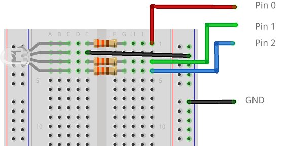
When you make this circuit, make sure that you connect the longest pin of the RGB LED to GND. If you get the other ones in the wrong order, it will be easy to change them when you test your program.
Programming - Digital
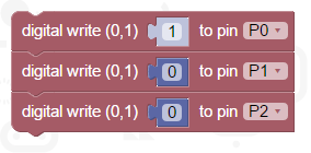
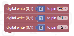
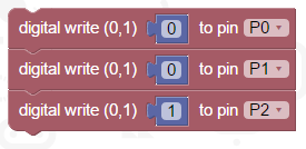
We can use digital write blocks to turn the different colours of LED on and off,
Red
Green
Blue
Challenge
You can turn on more than one of the colours at a time. When more than one coloured LED is on, the overall colour is a blend of the LEDs. Find out what colours you get for each combination,
- RED + GREEN
- RED + BLUE
- GREEN + BLUE
- RED + GREEN + BLUE
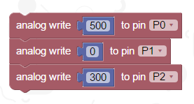
Programming - Analogue
Using analog write, you can combine different amounts of each colour to generate light of a very wide range of colours.
Challenges
- Turn your micro:bit into a mood light. A mood light changes colour slowly, glows and fades nicely from one colour to another. Use loops, analog write blocks and delays in your code to create a pattern of colours with the RGB LED.
- Use buttons or tilting to allow the user to select the colour of the LED somehow.