Computer Science
Data Representation
Program Design
Hardware & Software
Networks
Databases
Data Structures
Algorithms
Other
![]()


Computer Science
Error Detection & Correction
The character coding schemes were created to ensure that reliable digital communication. Establishing standards for character encoding is only the first step. You also have to consider how to detect whether or not errors have occurred in the transmission of data.
Single Parity Bit
Parity bits are the simplest form of error detection. A single bit is added to the bit pattern being transmitted so that there is either an odd or even number of "on" bits.
With odd parity, the sending computer adds a bit to the binary pattern and sets its value to 1 or 0 so that the total number of 1s is an odd number. The receiving device knows that an error has occurred with any patterns that have an even number of on bits and request that these messages are sent again.
Even parity does the same thing except that it ensures an even total number of 1s in the pattern.
For example, imagine transmitting the ASCII character, "A" (binary pattern, 1000001) using odd parity. The transmitting computer would add a parity bit with the value 1. This creates the pattern 11000001. The receiving computer recalculates the parity bit and compares its calculation to the data received. If the parity bit matches the one calculated, confirmation of receipt of the message is sent, if it does not, a request for re-transmission is sent.
Majority Rules
This is another very simple approach to error detection. If each bit is sent 3 times, the receiving computer might reasonably assume that the correct bit value is the one contained in the majority of the transmissions.
Hamming Code
Hamming code was invented by a chap called Richard Hamming (who is no the little guy on Top Gear). It goes a little further than simply checking for errors and can potentially correct single errors that occur in the transmission of a binary pattern.
The Rules
- All bit positions that are powers of 2 are parity bits (1, 2, 4, 8, 16, etc.)
- All other bit positions are used to represent the data to be encoded.
- Even parity is used.
- The bits that are used to determine the value of each parity bit depend on which parity bit is set.
For parity bit position n: skip n - 1 bits, check n bits, skip n bits, check n bits,
P1: n = 1, skip 0, check 1, skip 1, check 1, ...
P2: n = 2, skip 1, check 2, skip 2, check 2, ...
P3: n = 4, skip 3, check 4, skip 4, check 4, ...
P4: n = 8, skip 7, check 8, skip 8, check 8, ...
In the following example, the bit pattern for an ASCII H (1001000) is prepared for transmission using Hamming Code.
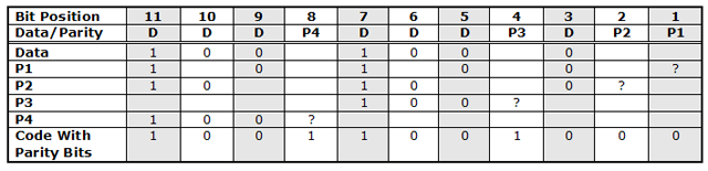
Check how this example implements the rules described above. For parity bit P1, we skip 0 positions then check 1. The first place we check is position 1. This is where parity bit 1 will be located so we write a question mark at this point. We then skip position 2, write in the value of the bit at position 3, skip 4, write in 5 etc. There is already an even number of 1s in the P1 row so we make the parity bit at P1 a 0.
Now, imagine that the H had been sent incorrectly and the bit pattern 10111001000 had been received instead of the correct pattern.
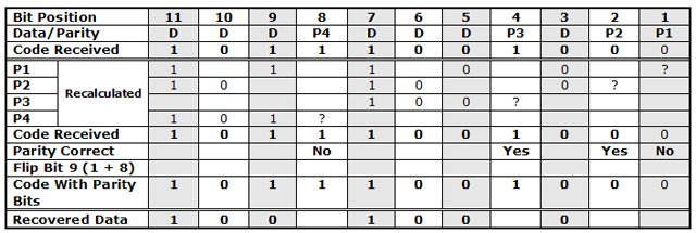
When we locate the parity bits which are not correct, we find that they are in bit positions 1 and 8. Adding those two numbers together gives us the position of the incorrect bit in the message (position 9). Flipping that bit corrects the message.
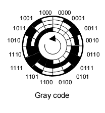
Gray Code
Frank Gray is generally held to be responsible for Gray code or Binary Reflected Gray Code (BRGC).
Study the following table carefully. You will see that each number requires only 1 bit to be changed for it to be transformed into the next or previous. You can also see that the numbers 8 - 15 are a reflection of the patterns for the numbers 0 - 7.
| Decimal | Pure Binary | Gray Code |
|---|---|---|
| 0 | 0000 | 0000 |
| 1 | 0001 | 0001 |
| 2 | 0010 | 0011 |
| 3 | 0011 | 0010 |
| 4 | 0100 | 0110 |
| 5 | 0101 | 0111 |
| 6 | 0110 | 0101 |
| 7 | 0111 | 0100 |
| 8 | 1000 | 1100 |
| 9 | 1001 | 1101 |
| 10 | 1010 | 1111 |
| 11 | 1011 | 1110 |
| 12 | 1100 | 1010 |
| 13 | 1101 | 1011 |
| 14 | 1110 | 1001 |
| 15 | 1111 | 1000 |
Gray code is widely used in angle movement systems to measure angle positions. In such cases, a rotary encoder may be used. A masked wheel can be read with photocells, looking something like the diagram below,