Computer Science
Data Representation
Program Design
Hardware & Software
Networks
Databases
Data Structures
Algorithms
Other
![]()


Computer Science
Logic Gates - Diagrams
Symbols
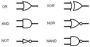
The following tables show the symbols that you should use in your circuit diagrams. Although the symbols are new to you, you will quickly spot the easy ways to remember which one is which.
We can construct circuits from boolean expressions or derive boolean expressions from our circuit diagrams. The following circuit diagram represents the boolean expression Q = A.B + C.D.
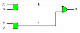
The labels E & F can be used as an intermediate stage to writing an expression for the circuit solely in terms of its inputs.
For example,
E = A.B
F = C.D
Q = E + F
Q = A.B + C.D
Example
Consider the following circuit diagram.
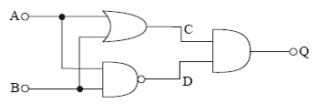
We can write out a truth table for this diagram to show its logic operates.
| A | B | C | D | Q |
|---|---|---|---|---|
| 0 | 0 | 0 | 1 | 0 |
| 0 | 1 | 1 | 1 | 1 |
| 1 | 0 | 1 | 1 | 1 |
| 1 | 1 | 1 | 0 | 0 |
Column C is A + B (A OR B), Column D is A.B (A NAND B) and Q is C.D (C AND D).
Looking carefully at the truth table, we can see that this circuit performs the same logic as the XOR gate.