Raspberry Pi Pico
MicroPython - Basics
MicroPython - More Involved
MicroPython - Pico W
MicroPython - micro:bit
MicroPython - Projects
CircuitPython - Some Basics
CircuitPython - HID Adventures
CircuitPython - Experiments
Other Pages
![]()


Raspberry Pi Pico
Blinking An LED
When starting with a new microcontroller, it makes sense to work out how to control LEDs.
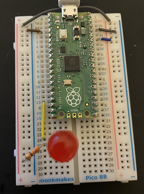
I am using the Monk Makes breadboard in this photograph. This is a standard half-size breadboard with numbering for the Pico pins. I have a large red LED with the anode (long pin) connected to pin 13 (for no special reason other than that was where my wire landed). The LED is connected to ground using a 330 OHM resistor.
It can be easy to become confused about the pin numbers and labels being used. Look at the following pinout diagram for the Pico.
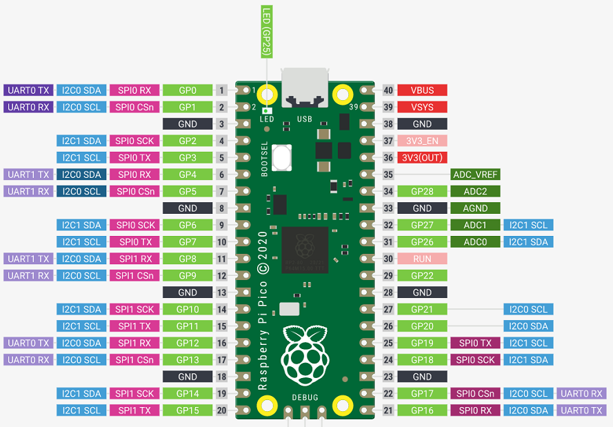
The pins on the printed circuit board are numbered from 1 to 40. The items labelled GPXX are the ones we are interested in. These are GPIO (general purpose input output) pins and are the ones we connect our components to.
Here is a Fritzing diagram for our circuit.
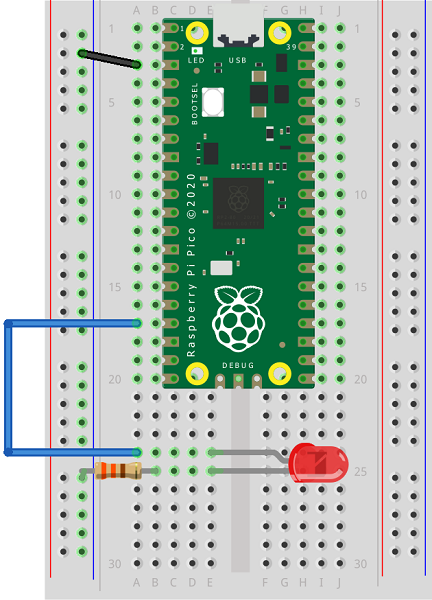
We start by making a connection from one of the ground (GND) pins to the left hand ground rail. The red (positive) and blue (negative) power rails are connected vertically on a breadboard. The others are connected horizontally in groups of 5.
When I place an LED in a breadboard I always place the anode (longer, positive leg) in the hole nearest the top of the breadboard. Because I always do that, I always know which is the longer leg without having to remove the LED from the breadboard to check.
Next, bend the resistor into an the shape of an upside down U. Then connect the row with the shorter LED leg to the GND power rail.
Finally, add a jumper cable to the row of the breadboard with the longer LED leg and connect it to the row with GP13 on the Pico.
When using an LED, the resistor is placed 'in series'. That means it need to be placed somewhere along the line of connections between the Pico pin and ground. In this circuit, it has been placed on the ground side of the LED. It could just as easily be placed on the positive side.
Programming - Method 1
Type the following code into Thonny and save to the Pico with the name main.py. Then press the play button to run the program on the Pico. You should get an LED blinking on and off every half second.
from machine import Pin
from time import sleep

led = Pin(13, Pin.OUT)

while True:
    led.value(1)
    sleep(0.5)
    led.value(0)
    sleep(0.5)
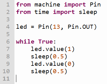
Let's look at this code a little more closely. The first two lines are import statements. We use these to let the microcontroller know which code modules we want to use in our program. The machine module is used for most of the interactions we need with the Pico. The time module gives us some extra functions for working with time periods.
On line 4, we use a variable to represent our connected component. The right hand side of this expression is configuring the GPIO pin (13 in this case) to be an output pin.
Line 6 marks the beginning of an infinite loop.
Line 7 shows how we can turn our LED on. This sets the signal from the GPIO pin to HIGH. Line 9 turns the LED off by setting the pin to LOW. Lines 8 and 10 make a half second pause.
Programming - Method 2 - Toggling
Another way to achieve the same effect is to toggle the pin. This simply flips the state from on to off. It means that we can write slightly less code,
from machine import Pin
from time import sleep

led = Pin(13, Pin.OUT)

while True:
    led.toggle()
    sleep(0.5)
The toggle method is going to be useful in our programs if all we are concerned with is swapping the state of a pin. It is less useful when we are choosing specifically whether it is on or off.
Programming - Method 3 - Timer
A third way to get the same effect is by using a timer.
from machine import Pin, Timer
from time import sleep

led = Pin(13, Pin.OUT)
tmr = Timer()

def blinker(tmr):
    led.toggle()

tmr.init(period = 500, mode = Timer.PERIODIC, callback = blinker)
We have to do a little more work this time but it may well be worth it in some projects. We define a timer and then write a subroutine that is going to be executed every time the timer ticks. We initialise our timer, telling it how often we want it to tick (the period), whether it is going to tick repeatedly or only once (PERIODIC or ONE_SHOT) and which subroutine to run on each tick (the callback). Once our periodic timer is initialised, it continues to run whilst the Pico is powered. A one-shot timer is a countdown to an event you want to happen once.
The Pico has a built-in LED connected to GP25. We can use this to do other things whilst the timer is ticking here so that we can see that we can use this technique to do more than one thing at once.
from machine import Pin, Timer
from time import sleep

led = Pin(13, Pin.OUT)
pico_led = Pin(25, Pin.OUT)

tmr = Timer()

def blinker(tmr):
    led.toggle()

tmr.init(period = 500, mode = Timer.PERIODIC, callback = blinker)

while True:
    pico_led.toggle()
    sleep(0.25)
We could also use a second timer to achieve the same effect.
from machine import Pin, Timer
from time import sleep

led = Pin(13, Pin.OUT)
pico_led = Pin(25, Pin.OUT)

ledtmr = Timer()
picotmr = Timer()

def blinker(tmr):
    if tmr==ledtmr:
        led.toggle()
    else:
        pico_led.toggle()

ledtmr.init(period = 500, mode = Timer.PERIODIC, callback = blinker)
picotmr.init(period = 250, mode = Timer.PERIODIC, callback = blinker)
Notice that we can use the same callback for both timers. The argument tmr can be checked to see which timer made the call, allowing us to act accordingly.
The timers are software timers and you can have as many of them asyou want in your program. Whether you go for using multiple timers like this, using while loops or a combination of the two is going to depend on the project you are making as well as your own preferences for your programs.