Raspberry Pi Pico
MicroPython - Basics
MicroPython - More Involved
MicroPython - Pico W
MicroPython - micro:bit
MicroPython - Projects
CircuitPython - Some Basics
CircuitPython - HID Adventures
CircuitPython - Experiments
Other Pages
![]()


Raspberry Pi Pico
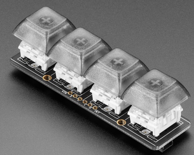
NeoKey 1x4 QT I2C Breakout
The NeoKey 1x4 QT I2C Breakout is a really nice breakout board from Adafruit. It is a circuit board that provides swappable sockets for mechanical keyboard switches (anything with a Cherry MX footprint). There is a Neopixel for each button. The whole thing is controlled over I2C using Adafruit's seesaw platform. I have copied an Adafruit photograph here because I did not want my poor photography to do a disservice to the product.
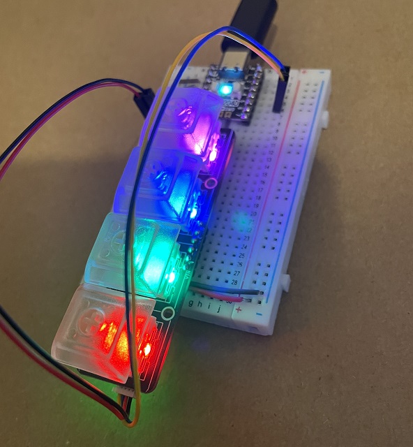
Here is the product in use. I have used a Stemma QT to Male header cable to connect to my Pimoroni Tiny 2040. I have the Neokey connected to I2C pins 4 and 5. Where you have a Pico with a stemma QT connector, you could do a direct connection without the need for the breadboard at all.
I have already used this breakout with CircuitPython. Since you are importing well written libraries, it 'just works' for you. I wanted to play around and see how easy (or difficult) it would be to get it working for MicroPython. It turned out to be quite a mission. The reason for this is that it is one of many Adafruit products that make use of the seesaw platform. The platform is really well-developed and highly versatile. There is a full core library for seesaw, another for working with Neopixels on the platform and another one for the Neokey breakout itself. Add to that the libaries for working with I2C devices and there is a lot of abstraction to unpack to port this over to MicroPython. This has made it a fun if, at times, a challenging project.
Programming
There are lots of ways that this project could have been approached and I may find myself having a go at doing that in future. For this first go at the task, I wanted to stick to using the Stemma QT connector only and not looking at the hardware interrupt pin.
Here is my start at a library for the board. I have left in many of the constants from the CircuitPython library but have removed some of the ones for features just not being used. There are two methods for reading the keys. The first one is more basic and just returns a nibble (4 bit number) indicating the states of the buttons. The second one reads the interrupt register first and only checks the button states if an interrupt is set. It returns -1 if no button state has changed.
from micropython import const
from time import sleep

_ADDR = const(48)

_STATUS_BASE = const(0x00)
_GPIO_BASE = const(0x01)
_INTERRUPT_BASE = const(0x0B)
_NEOPIXEL_BASE = const(0x0E)

_GPIO_DIRSET_BULK = const(0x02)
_GPIO_DIRCLR_BULK = const(0x03)
_GPIO_BULK = const(0x04)
_GPIO_BULK_SET = const(0x05)
_GPIO_BULK_CLR = const(0x06)
_GPIO_BULK_TOGGLE = const(0x07)
_GPIO_INTENSET = const(0x08)
_GPIO_INTENCLR = const(0x09)
_GPIO_INTFLAG = const(0x0A)
_GPIO_PULLENSET = const(0x0B)
_GPIO_PULLENCLR = const(0x0C)

_STATUS_HW_ID = const(0x01)
_STATUS_VERSION = const(0x02)
_STATUS_OPTIONS = const(0x03)
_STATUS_TEMP = const(0x04)
_STATUS_SWRST = const(0x7F)

_NEOPIXEL_STATUS = const(0x00)
_NEOPIXEL_PIN = const(0x01)
_NEOPIXEL_SPEED = const(0x02)
_NEOPIXEL_BUF_LENGTH = const(0x03)
_NEOPIXEL_BUF = const(0x04)
_NEOPIXEL_SHOW = const(0x05)

class NeoKey:

    def __init__(self, i2c):
        self.i2c = i2c
        # reset
        self.sw_reset()
        sleep(0.01)
        # check chip id
        chip = self.get_chip_id()
        if chip != 85:
            raise RuntimeError("Could not find the chip ID that was expected(85). Found: " + str(chip))
        # set gpio pins 4 - 7 and interrupt enable for now
        gpio = [0, 0, 0, 0b11110000]
        self.write_neokey(_GPIO_BASE, [_GPIO_DIRCLR_BULK] + gpio)
        self.write_neokey(_GPIO_BASE, [_GPIO_PULLENSET] + gpio)
        self.write_neokey(_GPIO_BASE, [_GPIO_BULK_SET] + gpio)
        sleep(0.01)
        self.write_neokey(_GPIO_BASE, [_GPIO_INTENSET] + gpio)
        # set neopixel details
        self.write_neokey(_NEOPIXEL_BASE, [_NEOPIXEL_PIN, 3])
        self.write_neokey(_NEOPIXEL_BASE, [_NEOPIXEL_BUF_LENGTH, 0,  12])
        self.neo_buffer = [
            _NEOPIXEL_BUF, 0, 0,
            0, 0, 0,
            0, 0, 0,
            0, 0, 0,
            0, 0, 0
            ]
        self.show()

    def write_neokey(self, base, lstbytes):
        self.i2c.writeto(_ADDR, bytes([base] + lstbytes))

    def read_neokey(self, n):
        return self.i2c.readfrom(_ADDR, n)

    def sw_reset(self):
        self.write_neokey(_STATUS_BASE, [_STATUS_SWRST, 0xFF])

    def get_chip_id(self):
        self.write_neokey(_STATUS_BASE, [_STATUS_HW_ID])
        sleep(0.001)
        return self.read_neokey(1)[0]

    # neokey pixels are GRB
    def set_colour(self, p, rgb):
        r, g, b = rgb
        self.neo_buffer[p * 3 + 3] = g
        self.neo_buffer[p * 3 + 4] = r
        self.neo_buffer[p * 3 + 5] = b

    def show(self):
        self.write_neokey(_NEOPIXEL_BASE, self.neo_buffer)
        self.write_neokey(_NEOPIXEL_BASE, [_NEOPIXEL_SHOW])

    def read_keystates(self):
        self.write_neokey(_GPIO_BASE, [_GPIO_BULK])
        sleep(0.001)
        keys = self.read_neokey(4)
        pattern = keys[3] ^ 255
        return pattern >> 4

    # checks interrupts, returns -1 if no change
    def read_btns(self):
        self.write_neokey(_GPIO_BASE, [_GPIO_INTFLAG])
        sleep(0.001)
        ints = self.read_neokey(4)
        ints = ints[3]  >> 4
        if ints != 0:
            self.write_neokey(_GPIO_BASE, [_GPIO_BULK])
            sleep(0.001)
            keys = self.read_neokey(4)
            pattern = keys[3] ^ 255
            return pattern >> 4
        else:
            return -1
Here is my basic test code to indicate proof of concept. There is much to develop and improve but this seems to work nicely enough.
from machine import Pin, I2C
from time import sleep
from neokey import NeoKey

pressed = [(255, 0, 0), (0, 255, 0), (0, 0, 255), (255, 0, 255)]
released = [(32, 0, 0), (0, 32, 0), (0, 0, 32), (32, 0, 32)]

i2c=I2C(0,sda=Pin(4), scl=Pin(5))

nkey = NeoKey(i2c)

def set_pad(p, on=True):
    if on:
        nkey.set_colour(p, pressed[p])
    else:
        nkey.set_colour(p, released[p])
    nkey.show()

last = 0

while True:
    reading = nkey.read_btns()
    if reading != -1:
        #print('{:04b}'.format(reading)) # test binary pattern
        for i in range(4):
            if reading >> i & 1:
                set_pad(i)
                print("Button", i, "pressed.")
            else:
                set_pad(i, False)
        last = reading
    sleep(0.05)
From the example code, you can see the point in the loop where button presses are being detected. There are several samples of button reading logic dotted around this section of the site, some in the CircuitPython section. You could use these to detect press and release events separately, prevent or ignore multiple presses and so on. Until I come back to this board, this page will serve as a reminder for me of how to get something from the board.