Raspberry Pi Pico
MicroPython - Basics
MicroPython - More Involved
MicroPython - Pico W
MicroPython - micro:bit
MicroPython - Projects
CircuitPython - Some Basics
CircuitPython - HID Adventures
CircuitPython - Experiments
Other Pages
![]()


Raspberry Pi Pico
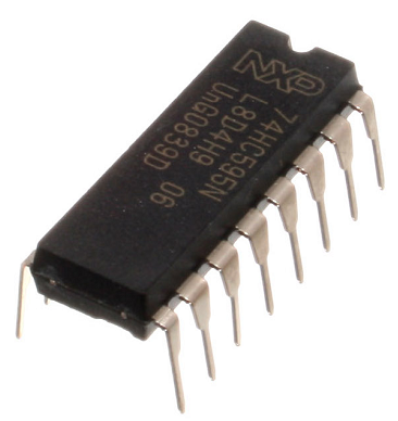
74HC595 Shift Register
The 74HC595 shift register is an integrated circuit that converts serial information to parallel. It requires 3 pins (as well as power) from the microcontroller but allows us to have a total of 8 outputs.
In this page, I will demonstrate how to use the IC to control 8 LEDs with 3 GPIO pins.
Here is a pinout diagram for the shift register,
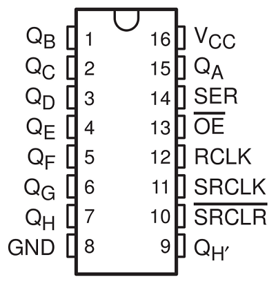
The pins labelled QA – QH are the outputs for our LEDs. VCC is where we connect our 3V power rail and GND is our ground. OE stands for output enable. The integrated circuit is enabled when we connect this to ground. We also need to connect SRCLR to 3V to use the circuit.
SER is our data pin, SRCLK is our clock pin and RCLK is our latch. The way the shift register works is that you set the data pin to the first value you want to shift out and then switch the clock pin from high to low to clock in that value. You do this for all 8 values and then switch the latch pin from high to low to output the whole set of values to the IC.
The QH' pin allows you to chain the output of this shift register to another one. When you do this, connect the latches and clocks together. QH' becomes the data pin for the second shift register. To shift in two bytes, you clock in all 16 values before toggling the latch.
Here is a photograph of my setup, with the data, clock and latch pins connected to GP6, GP7 and GP8 respectively,
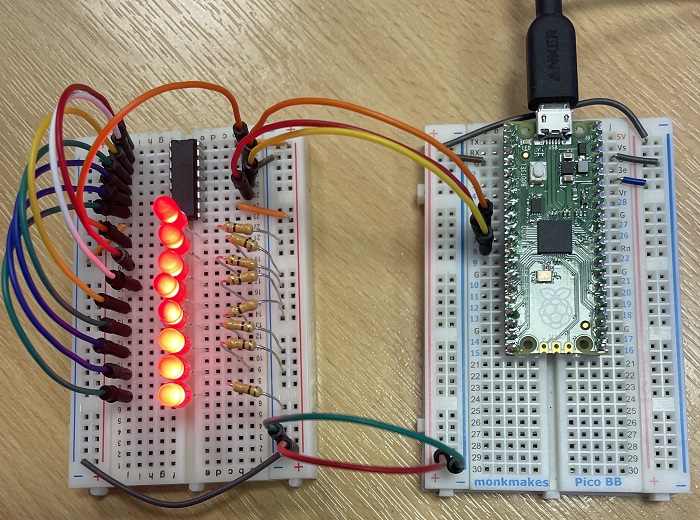
When you first try to build a circuit like this, it is worth taking your time and trying your best to be tidy.
Here is a Fritzing of a similar circuit,

When using diagrams like this, you don't need to place pieces in the exact locations. Use the diagram to tell you what needs to connect to what and then place things where the parts fit and make sense to you.
The following program has as subroutine defined for doing the shifting. The line with the list slicing bits = bits[::-1] can be removed to have the values shifted in to the other end of the group of LEDs.
from machine import Pin
from time import sleep

data = Pin(6, Pin.OUT)
clock = Pin(7, Pin.OUT)
latch = Pin(8, Pin.OUT)

# subroutine to shift binary data out
def shift_out(n, d, c, l):
    d.value(0)
    c.value(0)
    l.value(0)
    bits = [n >> i & 1 for i in range(8)]
    bits = bits[::-1]
    for i in range(8):
        d.value(bits[i])
        c.value(1)
        c.value(0)
    l.value(1)
    l.value(0)

for i in range(256):
    shift_out(i, data, clock, latch)
    sleep(0.1)
Using binary values has some advantages when we want to animate the LEDs. In the following program, I use left and right logical shifts to create an animation effect on the LEDs.
from machine import Pin
from time import sleep

data = Pin(6, Pin.OUT)
clock = Pin(7, Pin.OUT)
latch = Pin(8, Pin.OUT)

# subroutine to shift binary data out
def shift_out(n, d, c, l):
    d.value(0)
    c.value(0)
    l.value(0)
    bits = [n >> i & 1 for i in range(8)]
    bits = bits[::-1]
    for i in range(8):
        d.value(bits[i])
        c.value(1)
        c.value(0)
    l.value(1)
    l.value(0)

counter = 7
shift_out(counter, data, clock, latch)
while True:
    for i in range(5):
        counter = counter << 1
        shift_out(counter, data, clock, latch)
        sleep(0.1)
    for i in range(5):
        counter = counter >> 1
        shift_out(counter, data, clock, latch)
        sleep(0.1)