Raspberry Pi Pico
MicroPython - Basics
MicroPython - More Involved
MicroPython - Pico W
MicroPython - micro:bit
MicroPython - Projects
CircuitPython - Some Basics
CircuitPython - HID Adventures
CircuitPython - Experiments
Other Pages
![]()


Raspberry Pi Pico
PCF8574A Port Expander
The PCF8574A is 16-pin integrated circuit. You connect to it using the I2C protocol and it provides 8 input/output pins that can be used for a variety of devices. It is under a pound a chip and fairly easy to work with.
Here is the pinout for the chip,
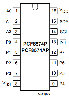
The pins A0 - A2 are address pins. Connecting them to power or GND in different combinations sets the I2C address. You could have 8 of these connected to the same bus.
The INT pin is an interrupt pin. If you connect this to a GPIO and treat it like a button, you get an interrupt fire whenever there is a button press or release on any of the buttons you connect to the P0 - P7 pins.
8 Inputs
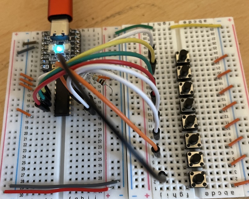
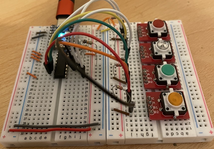
This is my test circuit for 8 pushbuttons. I used the Tiny 2040 here and managed to keep my wiring pretty tidy. In the image, you can just make out a 10K resistor connecting the 3V3 supply to one of the I2C pins. In fact, there is one of these for both SDA and SCL. Many microcontrollers have pull-up resistors connected to their I2C pins. Since these could be almost any of the GPIO, you need to add them for devices that don't have them. You might also be able to make out that I connected all 3 of the address pins to GND for an address of 0x38 (from the datasheet).
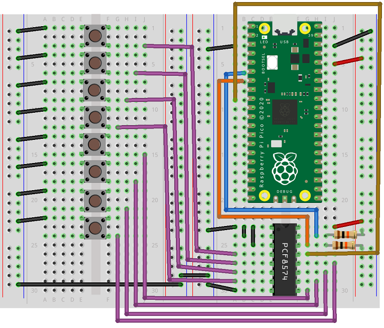
I found it harder to make a Fritzing diagram that looks as neat as my actual circuit. I find the pinout diagram for the chip the easiest thing to use when connecting to integrated circuits.
This was my first test program using an interrupt handler. It prints out a binary pattern to indicate which buttons are held down. It does this on press and release. A 0 is shown when a button is pressed, a 1 when not. The leftmost place value is button 7, the rightmost place value is button 0. You can use this program to test your wiring. If you see predictable changes in the binary pattern being output, then your wiring is probably good.
from machine import Pin, I2C

i2c = I2C(0,sda=Pin(4), scl = Pin(5))
i2c.writeto(0x38, b'\xff') # input mode
int_pin = Pin(7, Pin.IN, Pin.PULL_UP)

# subroutine to handle change of button state
def btn_handler(pin):
    a = i2c.readfrom(0x38,1)[0]
    print('{:08b}'.format(a))

# attach IRQ to button pin
int_pin.irq(trigger=Pin.IRQ_FALLING, handler=btn_handler)
If you do a logical XOR between the result and 255, you can invert the values to use 1 for pressed.
from machine import Pin, I2C

i2c = I2C(0,sda=Pin(4), scl = Pin(5))
i2c.writeto(0x38, b'\xff') # input mode
int_pin = Pin(7, Pin.IN, Pin.PULL_UP)

# subroutine to handle change of button state
def btn_handler(pin):
    a = i2c.readfrom(0x38,1)[0]
    a = a ^ 255
    print('{:08b}'.format(a))

# attach IRQ to button pin
int_pin.irq(trigger=Pin.IRQ_FALLING, handler=btn_handler)
If you want a way to use interrupts and spot when individual buttons are pressed or released, you can do that. In this program I took the previous and current state of each button in the button handler and I made a binary number out of them. So 01 meant a button was being pressed, 10 a button being released and 11 a button being held down since the previous reading.
from machine import Pin, I2C

i2c = I2C(0,sda=Pin(4), scl = Pin(5))
i2c.writeto(0x38, b'\xff') # input mode
int_pin = Pin(7, Pin.IN, Pin.PULL_UP)
last = 0

# subroutine to handle change of button state
def btn_handler(pin):
    global last
    a = i2c.readfrom(0x38,1)[0]
    a = a ^ 255
    btns = [((last >> i & 1)<<1) + (a >> i & 1) for i in range(8)]
    pressed = [i for i,e in enumerate(btns) if e==1]
    released = [i for i,e in enumerate(btns) if e==2]
    held = [i for i,e in enumerate(btns) if e==3]
    if len(pressed)>0:
        print("Pressed:", pressed)
    if len(released)>0:
        print("Released:", released)
    if len(held)>0:
        print("Held:", held)
    last = a

# attach IRQ to button pin
int_pin.irq(trigger=Pin.IRQ_FALLING, handler=btn_handler)
The interrupt handling is so quick that I can't manage to press buttons in such a way that multiple presses trigger a single interrupt. That means that the interrupt handling between the IC and the Pico is quick enough to pick out the press and release events individually. That may not be what you want in an particular application. You can, if you want, revert to using old fashioned polling as I have in this next program. I have put a few if statements in to check the states of particular buttons. I left it so that it is only looking for changes in button state. If you remove the comparison of the reading to the previous, you could check the button states each iteration.
from machine import Pin, I2C
from time import sleep

i2c = I2C(0,sda=Pin(4), scl = Pin(5))
i2c.writeto(0x38, b'\xff') # input mode
int_pin = Pin(7, Pin.IN, Pin.PULL_UP)
last = 0


while True:
    a = i2c.readfrom(0x38,1)[0]
    a = a ^ 255
    if a!=last:
        if a>>7 & 1:
            print("Button 7 is pressed")
        elif a>>6 & 1:
            print("Button 6 is pressed")
    last = a
    sleep(0.02)
8 Outputs
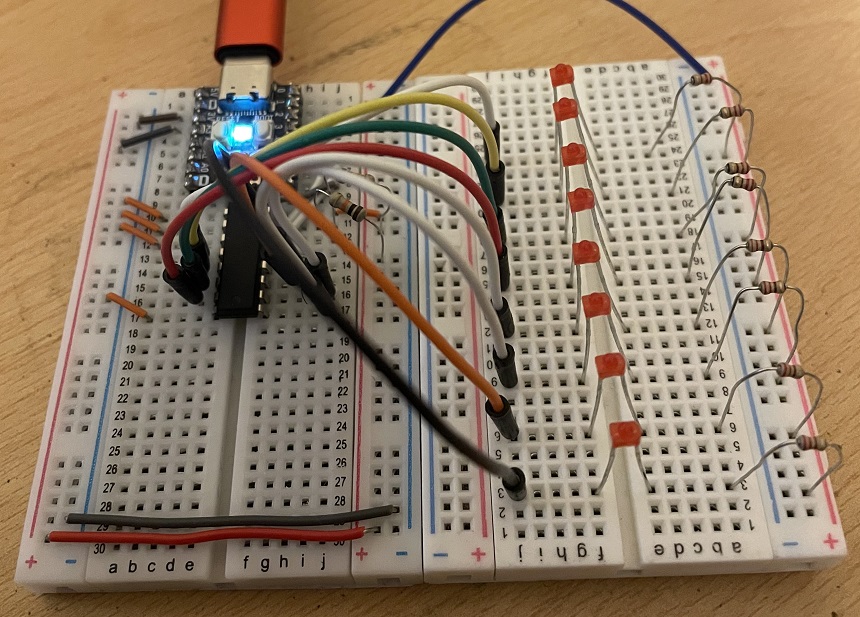
To connect LEDs to the port expander, you need to be aware that the chip cannot source current. That means that you connect the cathodes (short leg, negative) to the chip and the anodes (longer leg, positive) must be connected to your power supply. You need to connect a resistor for each LED. It can be connected to either pin of the LED but must be there. In this circuit, I have used a 220 Ohm resistor to connect each of my LEDs to the power supply.
As with the inputs, my circuit looks a little tidier than I can manage with the Fritzing diagram. It's here anyway,
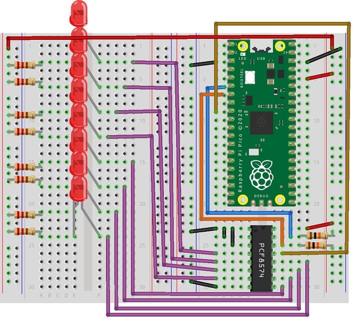
When doing output with LEDs, you have to set the pins to LOW in order to turn the LEDs on. I made a procedure to allow that to happen simply, using 1 for on and 0 for off.
from machine import Pin, I2C
from time import sleep

i2c = I2C(0,sda=Pin(4), scl = Pin(5))
i2c.writeto(0x38, b'\xff') # all off

# initial pattern for LEDs
leds = 0xff

# led 0 -7: 0 off, 1 on
def set_led(led, value):
    global leds
    if value==1:
        # turn on - set bit to 0
        leds = leds & (~(1<<led))
    elif value==0:
        # turn off - set bit to 1
        leds = leds | (1<<led)
    i2c.writeto(0x38, bytes([leds]))

# test one at a time
for i in range(8):
    set_led(i, 1)
    sleep(0.5)
    set_led(i , 0)
    sleep(0.5)

# all on
for i in range(8):
    set_led(i, 1)
sleep(3)
# all off
for i in range(8):
    set_led(i, 0)
Input & Output
For the last circuit, I have used 4 LED button boards. This can be recreated with separate LEDs and pushbuttons. I connected the LEDs to P4 - P7 and the pushbuttons to P0 - P3.
I tested this circuit out by combining my button reading code with the LED writing code. This time I left the logic as the chip needs it. With some bitwise logical shifting, you can use the reading you get for the buttons to get the pattern you need to write.
from machine import Pin, I2C

i2c = I2C(0,sda=Pin(4), scl = Pin(5))
i2c.writeto(0x38, b'\xff') # input mode and LEDS off
int_pin = Pin(7, Pin.IN, Pin.PULL_UP)

# subroutine to handle change of button state
def btn_handler(pin):
    a = i2c.readfrom(0x38,1)[0]
    btns = (a & 240)>> 4
    print('{:04b}'.format(btns))
    a = 240 + btns
    i2c.writeto(0x38, bytes([a]))

# attach IRQ to button pin
int_pin.irq(trigger=Pin.IRQ_FALLING, handler=btn_handler)