Raspberry Pi Pico
MicroPython - Basics
MicroPython - More Involved
MicroPython - Pico W
MicroPython - micro:bit
MicroPython - Projects
CircuitPython - Some Basics
CircuitPython - HID Adventures
CircuitPython - Experiments
Other Pages
![]()


Raspberry Pi Pico
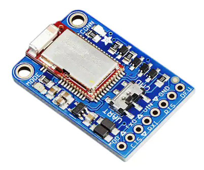
Bluefruit LE UART Friend
This page is about my new old favourite board to use with a microcontroller. I say 'new old' because I have had Adafruit's Bluefruit LE UART friend for a few years. I dug it out recently to try with the Pico and had just forgotten what a useful breakout board it is.
BLE stands for Bluetooth Low Energy, the later variety of bluetooth developed to work on mobile devices. The board is designed to make it easy to get interaction between your mobile phone and microcontroller. That accounts for the 'friend' part of the beakout's name. You use UART to make a serial connection between the breakout and the Pico.
Like all Adafruit products, this board is of the highest quality and has been really well thought out. Adafruit have made a mobile APP (IOS and Android) that you can use to communicate with the breakout and therefore with your project. It is called Bluefruit LE Connect and it works with a range of Adafruit BLE products. UK prices vary for this board. It is generally around £18 at the time of writing this page.
I have tried out the IOS version of the APP. I am assuming the same functionality in the Android version. The APP allows you to send and receive text between the phone and your project. There is a tool for plotting readings that you get from multiple sensors. There is also a colour picker, a control pad and a handful of other tools. Some of the tools require specific projects or hardware to be setup with your microcontroller and some are open for you to exploit for your own purposes. There is a lot that you can do with this board. I have enjoyed exploring some of its possiblities as much as I have liked to see it work nicely as a control system for a robot vehicle.
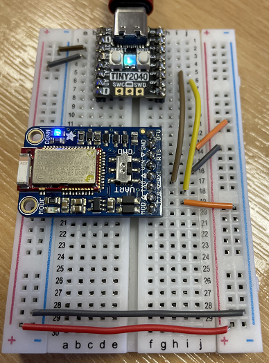
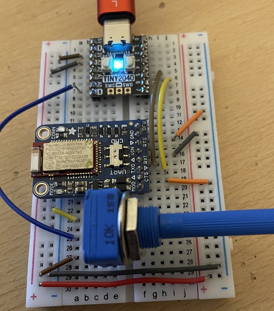
Here is a photo of the board connected to Pimoroni's Tiny 2040.
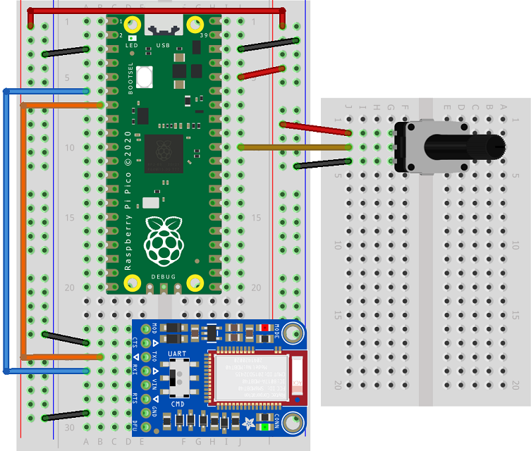
The Fritzing diagram shows the breakout connected to the equivalent RP2040 pins on the classic Pico,
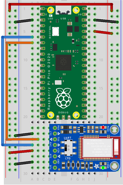
I have used GP4 for my tx pin (connected to rx on the breakout) and GP5 for my rx pin (connected to tx on the breakout). This is UART 1 on the Pico. Vin and GND are connected to 3V3 and GND respectively. The CTS pin also needs to be connected to GND.
Programming - UART
I started by using the UART module of the APP. This allows you to send and receive plain text between the Pico and the APP. When you open the APP, you need to connect to the breakout board and then open the UART module. When you type and send a message, it comes as a series of bytes representing the characters of your message. It adds an ASCII 10 at the end of the message - a new line character.
To test sending messages both ways, I added a pushbutton connected to GND and to GP26. I had a breakout that had its two pins next to each other which made it convenient. You could use a different pin and change the code accordingly.
from machine import Pin, UART
from time import sleep

uart = UART(1, baudrate=9600, tx=Pin(4), rx=Pin(5))

btn_a = Pin(26,Pin.IN,Pin.PULL_UP)

# subroutine to handle button presses
def btn_a_handler(pin):
    uart.write("Hello, Phone\n")

# attach IRQ to button pin
btn_a.irq(trigger=Pin.IRQ_FALLING, handler=btn_a_handler)

while True:
    if uart.any():
        d = uart.read()
        d = d.decode("utf-8")
        print(d)
    sleep(0.1)
The button is used to trigger the sending of a message from the project. You can type your message in the APP to send it to the Pico.
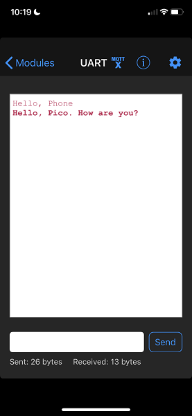
The bolder text is written in the APP itself, the regular text came from the project.
Simple as this application is, there are so many ways that this could be used in a project. Instead of printing the values received over UART, you could check whether or not they matched some commands you have defined to control hardware in your project. This could be as simple as having to type in specific words to turn LEDs or buzzers on. You might also send a command word to receive a reading from a sensor.
You could go a little further than this though. Simply having the ability to send and receive text like this means that you could design a command system. You might start with a list of the trigger words like,
- turn on
- turn off
- read
- write
- play
- stop
Your program could read the text it receives and look out for commands beginning with one of these. It could then read the last part of the input and determine what is to be turned on or off, or which items is to be read.
Programming - Plotter
The plotter is designed to let you see the way that analog readings change over time. You can have it plot multiple values on a continuous graph. You just need to organise the way that you send the data.
For a quick test, you want to set up any component that can give you analog values. I am using a potentiometer in this photograph, but you could also use something like a photoresistor or a flex sensor.
The Fritzing shows the equivalent circuit using a classic Pico.
Here was my test program,
from machine import Pin, UART, ADC
from time import sleep

uart = UART(1, baudrate=9600, tx=Pin(4), rx=Pin(5))
pot = ADC(26)


while True:
    d = uart.read()
    p = int(pot.read_u16())
    p = str(p) + "\n"
    msg = bytes([ord(c) for c in p])
    uart.write(msg)
    sleep(0.1)
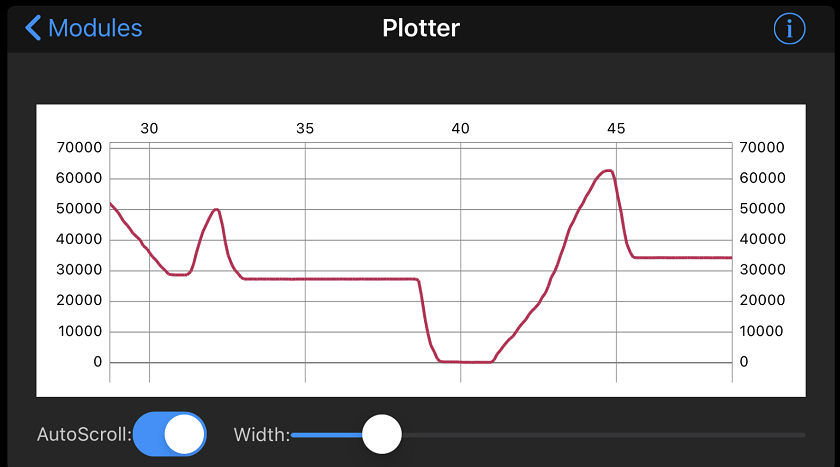
You have to send the ASCII characters for the values you want to plot. You can send multiple values separated with a comma. You need to send an ASCII 10 (newline) at the end of each group of plottable values. In this program, I am just sending the one value at a time. The Adafruit tutorials recommend sending no more than 10 readings per second. The plotter will automatically work out a scale for you and change it as you go.
Running the plotter module with this circuit and twisting the knob of the potentiometer gave me this,
Controller
The controller module has a handful of different subsections that send different data to the breakout from your phone. Messages from the APP come in the following format,
- Each Controller data packet sent is prefixed with single byte char "!" (0x21) followed by a single byte char initial for identification.
- Sensor data values are encoded as floats of 4 byte length.
- Each packet ends with a single byte checksum for validation.
Simple Test Program
Whichever of the features you are wanting to use in this module, you will need to get used to the way that the data packets are sent. The easiest way to do that is to simply look at them. A really simple program for this is,
from machine import Pin, UART
from time import sleep

uart = UART(1, baudrate=9600, tx=Pin(4), rx=Pin(5))


while True:
    if uart.any():
        d = uart.read()
        d = [i for i in d]
        print(d)
    sleep(0.1)
Control Pad
I used the test program with the control pad to see what kinds of value were being sent. I made a table of the values that I received,
| Prefix | Button | Button Number | Press or Release | Checksum | Button | Event |
|---|---|---|---|---|---|---|
| 33 | 66 | 49 | 49 | 58 | 1 | Press |
| 33 | 66 | 49 | 48 | 59 | 1 | Release |
| 33 | 66 | 50 | 49 | 57 | 2 | Press |
| 33 | 66 | 50 | 48 | 58 | 2 | Release |
| 33 | 66 | 51 | 49 | 56 | 3 | Press |
| 33 | 66 | 51 | 48 | 57 | 3 | Release |
| 33 | 66 | 52 | 49 | 55 | 4 | Press |
| 33 | 66 | 52 | 48 | 56 | 4 | Release |
| 33 | 66 | 53 | 49 | 54 | Up | Press |
| 33 | 66 | 53 | 48 | 55 | Up | Release |
| 33 | 66 | 54 | 49 | 53 | Down | Press |
| 33 | 66 | 54 | 48 | 54 | Down | Release |
| 33 | 66 | 55 | 49 | 52 | Left | Press |
| 33 | 66 | 55 | 48 | 53 | Left | Release |
| 33 | 66 | 56 | 49 | 51 | Right | Press |
| 33 | 66 | 56 | 48 | 52 | Right | Release |
So, the identifier for a button press is a 'B' the buttons send an ASCII value for characters 1 to 8. They also send a 0 or 1 to indicate whether or not the button is being pressed or released.
At first glance, the checksum can seem a little weird. Its purpose is to allow you to check whether or not you have received a valid packet of data. That last byte is calculated from the previous 4. With the controller module of the APP, the same checksum algorithm is used to get that last byte.
- Add all of the bytes together.
- Apply a logical NOT (invert the bits).
- Perform a logical AND with 255.
Let's try that out with the first row of our table,
Add together: 33 + 66 + 49 + 49 = 197
Invert bits: NOT(197) = NOT (11000101) = 00111010
AND with 255: 00111010 AND 11111111 = 00111010
00111010 = 58
The last step looks redundant when working by hand. When you do the NOT in a program, there are additional place values set to 1, and the whole number will be negative. Doing the AND with 255 will mask out those higher place values and give the single byte that we are looking for.
In experimenting with the control pad, I found a couple of issues. The control pad sends press and release messages for the buttons. If I assumed that a message was 5 bytes long, I would miss some of the messages. This meant that buttons would appear not to have been released or not to have been pressed. It was easy to make the messages more than 5 bytes when pressing multiple buttons.
The other issue was that I'm just not used to reading events like this for button presses. Normally I want to check the state. In a program that is polling inputs to check their state, I want to know if a button is currently pressed rather than respond to the button press event. This is important if you want to use the controller to make a robot vehicle turn left when both forward and left buttons are pressed. It should not be necessary to have to press them at the exact same time to get that behaviour.
In order to deal with getting more than 5 bytes, I just made a list of lists of the bytes. In order to make the states of the buttons readable, I used a byte. The bits are set and unset as and when the press and release messages are received. It is possible, therefore, to work out when more than one button is currently being held down by examining this byte. There is a function for that purpose in the code below. My program understands the buttons to be 0 to 7, rather than 1 to 8 so that the bits are numbered according to binary place values.
from machine import Pin, UART
from time import sleep

uart = UART(1, baudrate=9600, tx=Pin(4), rx=Pin(5))

# binary integer to store button states
pattern = 0
last = 0

def is_pressed(b):
    return pattern >> b & 1 == 1


while True:
    if uart.any():
        d = list(uart.read())
        d = [d[i:i+5] for i in range(0,len(d),5)]
        for b in d:
            if b[1]==66:
                btn =b[2]-49
                if b[3]==49:
                    pattern = pattern | (1<<btn)
                else:
                    pattern = pattern & ~(1<<btn)
    if pattern!=last:
        print('{:08b}'.format(pattern))
    last=pattern
Sensor Data
Choose one of the sensor data parts of the controller module and you can send readings from your phone's sensors to your project. The choices are,
- Quaternion: This sends data to describe the 'attitude' of the device. This comes in x, y, z form and is derived from readings taken from the accelerometer, magnetometer and gyroscope. These numbers are going to give you the most accurate way of telling how the phone is being tilted and which way it is facing.
- Accelerometer: This gives you raw readings from the accelerometer on the phone. It gives you a reasonable sense of the way you are tilting the device.
- Gyro: The gyroscope is used to measure angular velocity giving a sense of how the device is oriented.
- Magnetometer: This gives you raw magnetometer data. This is not calibrated. It is normal to use accelerometer readings to calibrate magnetometer readings. Use a compass application and you will normally be asked to rotate the phone before you can start to take readings. You can send this data to your phone anyway.
- Location: This gives you the GPS position of your phone.
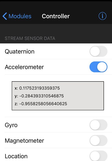
For all of the above except GPS, you get an x, y and z reading using a 4 byte floating point number. For the GPS, you get latitude, longitude and altitude. All of these use the same number of measurements and in the same format. You can use the same approach in the code to read them and just change the module on the phone. You can try them all out and find which one makes most sense for what you want in a project.
Here is what you see in the APP,
from machine import Pin, UART
from time import sleep
from ustruct import unpack
uart = UART(1, baudrate=9600, tx=Pin(4), rx=Pin(5))


while True:
    if uart.any():
        d = uart.read()
        d = [i for i in d]
        x = bytes(d[2:6])
        y = bytes(d[6:10])
        z = bytes(d[10:14])
        x = unpack('<f', x)[0]
        y = unpack('<f', y)[0]
        z = unpack('<f', z)[0]
        print(x,y,z,sep=',')
    sleep(0.1)
Of these, I quite like the GPS. With a little bit of experimentation and some basic programming, you can get a project to sense where it is being run and behave differently.
Colour Picker
The last module I tried was the colour picker. This looks like this,
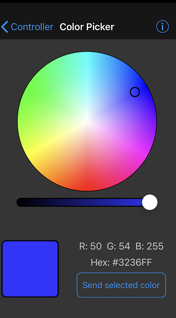
To test this out, I am using the built-in RGB LED on the Tiny 2040. Unlike many of the RGB LEDs that you use, this one is common anode. To get the right colours on this one, you need to subtract your colour from 255. If you are testing this program out with a common cathode RGB LED (like the one on the page in this site), take out those lines.
from machine import Pin, UART, PWM
from time import sleep
from math import floor
uart = UART(1, baudrate=9600, tx=Pin(4), rx=Pin(5))

red = PWM(Pin(18))
green = PWM(Pin(19))
blue = PWM(Pin(20))
red.freq(500)
green.freq(500)
blue.freq(500)

# r,g,b values from 0 to 255
# common anode RGB LED on Tiny 2040
def rgb(r,g,b):
    r = 255 - r
    g = 255 - g
    b = 255 - b
    red.duty_u16(floor(r/255*65535))
    green.duty_u16(floor(g/255*65535))
    blue.duty_u16(floor(b/255*65535))

while True:
    if uart.any():
        d = uart.read()
        dr = d[2]
        dg = d[3]
        db = d[4]
        rgb(dr,dg,db)
        print(dr,dg,db)
    sleep(0.1)
Summary
This board and the phone APP are absolutely brilliant. I really enjoyed testing out all of the features and having a little play with a couple of side projects. There are so many ways that you can use this breakout to bring your phone into play with your microcontroller project. The control pad is great for directing your robot friend vehicle. The UART interface is going to be my goto keyboard for my future projects.