Other
Arduino - LED Projects
Arduino - Buzzer Projects
Arduino - Midi Projects
Arduino - Microview
Arduino - Other Projects
Arduino - Visual Basic.NET
Arduino - Tim's Projects
Arduino - Links
![]()


Bar Graph
Introduction
This project explores a couple of ways of simulating and using a bar graph with the Arduino. Bar graph components like the following one can be used,
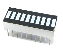
This type of bar graph is basically just 10 LEDs in a row with anodes on one side of the component and cathodes on the other.
The same thing can be created by just placing 10 LEDs on a breadboard. If you have LEDs smaller than 5mm, you may be able to get them closer together on the breadboard. If not, just space out as you see in the diagrams.
You Will Need
- 10 x LEDs or 1 x 10 Segement Bar Graph
- 10 x 330 Ohm Resistors
- 10K Trimmer Potentiometer
- 1 x Piezo Buzzer
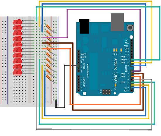
Making The Circuit - Bar Graph
The first job is to connect up all of those LEDs and resistors to make the bar graph.
Programming The Arduino - Bar Graph
Here is some code to test that the bar graph has been wired correctly.
int ledPin[] = {1,2,3,4,5,6,7,8,9,10};

void setup()

{

  for (int i =0;i<10;i++)

  {

    pinMode(ledPin[i], OUTPUT);

  }

}


void loop()

{

  upanddown();

  delay(1000);

  oneatatime();

  delay(1000);


}

void alloff()

{

  for (int i =0;i<10;i++)

  {

    digitalWrite(ledPin[i], LOW);

  }

}


void allon()

{

  for (int i =0;i<10;i++)

  {

    digitalWrite(ledPin[i], HIGH);

  }

}


void showUpTo(byte numtoshow)

{

  alloff();

  for (byte i = 0;i<numtoshow;i++)

  {

    digitalWrite(ledPin[i],HIGH);

  }


}

void upanddown()

{

  for (int i =0;i<10;i++)

  {

    digitalWrite(ledPin[i], HIGH);

    delay(100);

  }

  for (int i=9;i>=0;i--)

  {

    digitalWrite(ledPin[i], LOW);

    delay(100);

  }

}

void oneatatime()

{

  for (int i =0;i<10;i++)

  {

    digitalWrite(ledPin[i], HIGH);

    delay(100);

    digitalWrite(ledPin[i], LOW);

    delay(100);

  }

}
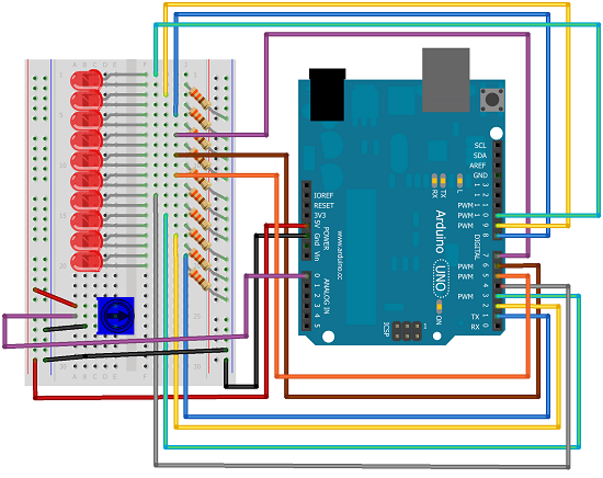
Making The Circuit - Trimpot
Adding a trimpot to control the bar graph allows the bar graph to be used as an indicator for the position of the potentiometer.
Programming The Arduino - Trimpot
int ledPin[] = {1,2,3,4,5,6,7,8,9,10};

int potPin = A0;

void setup()

{

  for (int i =0;i<10;i++)

  {

    pinMode(ledPin[i], OUTPUT);

  }

}


void loop()

{

fromPot();

}


void alloff()

{

  for (int i =0;i<10;i++)

  {

    digitalWrite(ledPin[i], LOW);

  }

}


void allon()

{

  for (int i =0;i<10;i++)

  {

    digitalWrite(ledPin[i], HIGH);

  }

}


void showUpTo(byte numtoshow)

{

  alloff();

  for (byte i = 0;i<numtoshow;i++)

  {

    digitalWrite(ledPin[i],HIGH);

  }


}

void fromPot()

{

  int potvalue = analogRead(potPin);

  byte show = map(potvalue,0, 1023, 0,10);

  showUpTo(show);

}


void upanddown()

{

  for (int i =0;i<10;i++)

  {

    digitalWrite(ledPin[i], HIGH);

    delay(100);

  }

  for (int i=9;i>=0;i--)

  {

    digitalWrite(ledPin[i], LOW);

    delay(100);

  }

}

void oneatatime()

{

  for (int i =0;i<10;i++)

  {

    digitalWrite(ledPin[i], HIGH);

    delay(100);

    digitalWrite(ledPin[i], LOW);

    delay(100);

  }

}
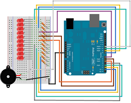
Making The Circuit - Buzzer
Now to make the buzzer and lights work together.
Programming The Arduino - Buzzer
The program includes definitions of the 10 natural notes that start with middle C. Each light represents a note and is switched on when the note is playing.
int buzzerPin = 11;

int tempo = 150;

int ledPin[] = {1,2,3,4,5,6,7,8,9,10};


int notes[] = {262,294,330,349,392,440,494,523,587,659};


int tunelength = 14;

int tune[] = {0,0,4,4,5,5,4,3,3,2,2,1,1,0};

int beats[] = {1, 1, 1, 1, 1, 1, 2, 1, 1, 1, 1, 1, 1, 2};


void setup()

{

  for (int i =0;i<10;i++)

  {

    pinMode(ledPin[i], OUTPUT);

  }

  pinMode(buzzerPin, OUTPUT);

}

void playTune()

{

  for (int i =0;i<tunelength;i++)

  {

    tone(buzzerPin, notes[tune[i]], beats[i]*tempo);

    digitalWrite(ledPin[tune[i]], HIGH);

    delay(beats[i]*tempo);

    digitalWrite(ledPin[tune[i]], LOW);

    delay(tempo/10);

  }


}

void loop()

{

  playTune();

  while(true){

  };

}


void alloff()

{

  for (int i =0;i<10;i++)

  {

    digitalWrite(ledPin[i], LOW);

  }

}


void allon()

{

  for (int i =0;i<10;i++)

  {

    digitalWrite(ledPin[i], HIGH);

  }

}


void showUpTo(byte numtoshow)

{

  alloff();

  for (byte i = 0;i<numtoshow;i++)

  {

    digitalWrite(ledPin[i],HIGH);

  }


}
Challenges
You could start by changing the tune in the buzzer version.
There are lots of other sensor values that you can use a bar graph with. A thermometer would be a starting point.
If you make 4 of the LEDs a different colour from the others, you have enough LEDs to do the output for a binary clock. (You'd be using 12hr format for the hour part of the time.) If you have access to a Real Time Clock module, you could use that to source your time components.Alternatively, you can look for the Time library on the Arduino web site and do a similar job without.