Other
Arduino - LED Projects
Arduino - Buzzer Projects
Arduino - Midi Projects
Arduino - Microview
Arduino - Other Projects
Arduino - Visual Basic.NET
Arduino - Tim's Projects
Arduino - Links
![]()


Shift Register
Introduction
This is quite a fiddly circuit to make - but it illustrates an important idea. When we want to control a large number of items, we will run out of pins on the Arduino very quickly. The shift register is an integrated circuit for converting serial input into parallel output. This allows us to use 3 pins to control 8 components.
You Will Need
- 8 x LEDs
- 8 x 330 Ohm Resistors
- 1 x Shift Register
- Jumper Wires
The 74HC595 shift register that comes with the Sparkfun Inventor's Kit looks like this,
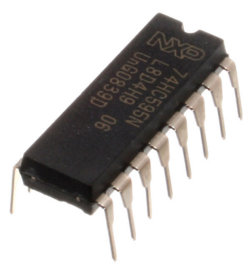
The notch at the top of the integrated circuit is important. It allows you to identify the pins of the chip from its datasheet.
The datasheet for this IC shows the following pinning information,
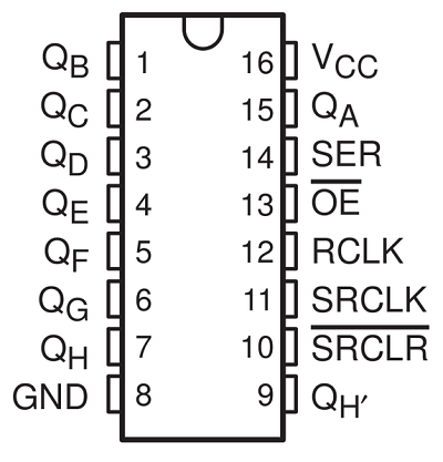
The pins labelled QA to QH are the 8 output pins. We will connect our 8 LEDs to these in order.
The pins labelled VCC and GND will be connected to 5V and GND respectively. We will also connect the pin labelled as SRCLR to 5V - this clears the shift register when pulled low, enables it when pulled high. OE or output enable is connected to GND to enable output.
The next set of important pins for us are SER or serial input. We will connect this to pin 2 and refer to it as our data pin. SRCLK or serial clock will be connected to pin 3 and will be referred to as our clock pin. Finally, RCLK or register clock will be connected to pin 4 and referred to as our latch pin.
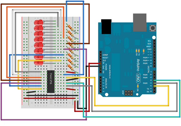
Making The Circuit
There is a lot of wiring in this circuit. Take care to place the connections in the right places. Start by placing the shift register the correct way up at the bottom of the breadboard. Then place all 8 of the LEDs. Make sure that you place the longer lead in the top of the two holes you use. Then, for each LED connect its positive pin and add a resistor connected to GND. Do this one at a time so you don't run out of room. Take care to make sure that the resistors don't touch one another. Finally make the connections to the shift register, working your way around the IC.
Programming The Arduino
With a complex load of wiring like we have here, the first thing to do is to check that we have everything placed correctly. This first code sample defines a writeByte procedure to allow binary values from 0 - 255 to be represented with the LEDs. Initially all of the LEDs are set to blink on and off so we can isolate any wiring problems we have.
int datapin = 2;

int clockpin = 3;

int latchpin = 4;


void setup()

{

  pinMode(datapin, OUTPUT);

  pinMode(clockpin, OUTPUT);

  pinMode(latchpin, OUTPUT);

}


void loop()

{

  writeByte(255);

  delay(500);

  writeByte(0);

  delay(500);

}


void writeByte(byte data)

{

  shiftOut(datapin, clockpin, MSBFIRST, data);

  // toggle the latch pin so that the data appears as an output

  digitalWrite(latchpin, HIGH);

  digitalWrite(latchpin, LOW);

}
Challenge
Use a for loop to get the LEDs to count up to 255 in binary.
Programming The Arduino - Controlling The Pins Individually
We can use the writeByte procedure to do this but it would be handy to have a simpler way to turn individual LEDs on and off. Add this procedure to your code and test that you can manipulate the LEDs one at a time.
void shiftWrite(int thePin, boolean theState)

{

  // create a byte with all of the place values at 0

  byte data = 0;

  // write a bit to the pin we want to turn on

  bitWrite(data,thePin,theState);

  // send the byte to the shift register

  shiftOut(datapin, clockpin, MSBFIRST, data);

  // toggle the latch pin so that the data appears as an output

  digitalWrite(latchpin, HIGH);

  digitalWrite(latchpin, LOW);

}
Challenges
Look up the pattern writing technique for the previous project. Work out some interesting patterns for this circuit.
If you declare the variable data as a global, you can use the shiftWrite procedure to turn pins individually without affecting the pins you already have on. Simply move the declaration to the top of the code window to do this. Try this way of making patterns of lights go on and off to see if you find it easier than using the byte as a whole each time.