Other
Arduino - LED Projects
Arduino - Buzzer Projects
Arduino - Midi Projects
Arduino - Microview
Arduino - Other Projects
Arduino - Visual Basic.NET
Arduino - Tim's Projects
Arduino - Links
![]()


Visual Basic Charlieplexing Assistant
Introduction
It would make most sense for you to have set up a basic charlieplexed matrix before doing anything on this page. The material on this page will help you understand the basic theory before going any further.
The following screenshot shows a basic application for helping set up charlieplexed matrices.
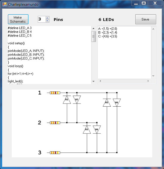
The user specifies the number of digital pins being used for the circuit. The program then calculates the number of LEDs that can be driven with the given number of pins. It also produces some basic Arduino code to use the matrix. The textbox on the right lists the LED anodes and cathodes connected to each pin.
Spotting Patterns
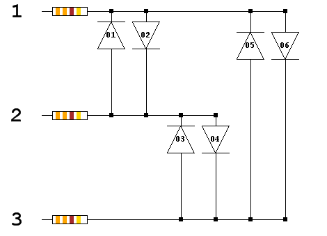
3 Pins
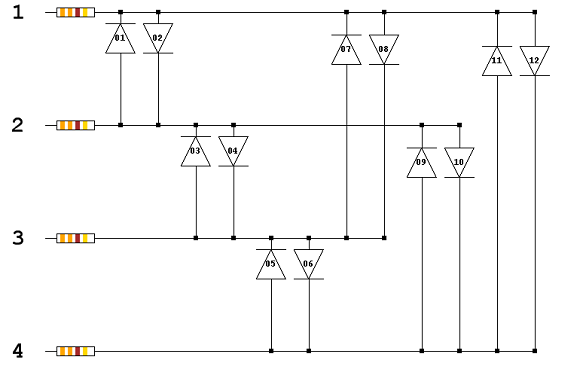
4 Pins
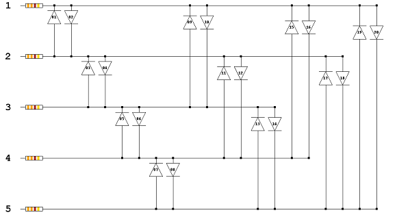
5 Pins
If you look carefully enough, you can see that there are some patterns in the way that these schematics change as the number of pins and LEDs increases.
The most obvious point is that the LEDs are connected in pairs. Each pair connects to the same two pins. The first LED in each pair has its cathode connected to the first pin and anode to the second pin. The second LED in each pair is connected the other way around.
The arrangement of the LEDs forms a triangular pattern in each schematic. Halving the number of LEDs in each schematic gives you a triangular number. The number of pairs of LEDs in each schematic is therefore a triangular number.
The next thing to notice is the distance between the pins that connect to each pair of LEDs. For example, in the 3 pin schematic, the first and second pairs are connected to pins that have a distance of 1 between them. The third pair is connected to pins with a distance of 2. This pattern continues as the number of pins and LEDs increases.
Programming
In order to produce the schematic or code in a program like this, you need to know which pins are connecting to each pair. As long as you know which pins are involved, you can assume that the first LED in each pair is connected cathode to first pin, anode to second pin and the second LED connected the other way around.
The following code generates two arrays that store this information. It is the basis for the program shown earlier,
Dim numCharlies = pins * (pins - 1)

Dim numPairs As Integer = numCharlies / 2

Dim lefties(numPairs - 1) As Integer

Dim righties(numPairs - 1) As Integer

Dim pair As Integer = 0

pair = 0

For i As Integer = pins - 1 To 1 Step -1

   For j As Integer = 0 To i - 1

      lefties(pair) = j + 1

      righties(pair) = j + pins - i + 1

      pair += 1

   Next

Next
Next Steps
Once you have seen the result of this code fragment, you should try to do something to make use of it. You can, of course, use the information to draw the schematic. An alternative is to produce a written explanation of how to connect the LEDs. It's a little easier to achieve than the schematic but no less useful. Finally, working out how to generate code for a given number of pins leaves you a very useful program.