Other
Arduino - LED Projects
Arduino - Buzzer Projects
Arduino - Midi Projects
Arduino - Microview
Arduino - Other Projects
Arduino - Visual Basic.NET
Arduino - Tim's Projects
Arduino - Links
![]()


DIY LED Matrix
Introduction
An LED matrix is another way of connecting multiple LEDs together, reducing the number of digital pins required to drive the display. A variety of these components is available to purchase, usually with 64 LEDs arranged in an 8x8 grid. This page shows how a 3x3 matrix can be set up on a solderless breadboard.
You Will Need
- 9 x LEDs
- 3 x 330 Ohm Resistors
- Jumper Wires
- Extra Solderless Breadboards
Making The Circuit
The LEDs in this diagram are shown as red circles with + and - indicating which pin goes where.
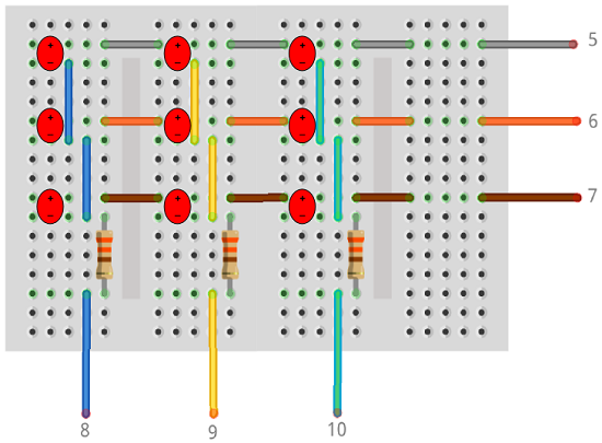
Notice that the anodes of each row are connected together, the cathodes of each columns are also connected together. Instead of using 9 pins to drive these LEDs, we are using 6.
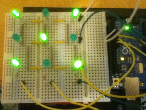
Below is a photograph of this arrangement being used on some solderless breadboards that have been connected together.
Programming The Arduino - Testing
First, we need to check that we can light each of the LEDs individually. This code lights up the LED in the middle of the matrix,
// anodes

int row[] = {5,6,7};

// cathodes

int col[] = {8,9,10};


void setup()

{

  for (int i=0;i<3;i++)

  {

    pinMode(row[i], OUTPUT);

    pinMode(col[i], OUTPUT);

  }

  allOff();

}


void loop()

{

  digitalWrite(row[1], HIGH);

  digitalWrite(col[1], LOW);

}


void allOff()

{

  for (int i=0;i<3;i++)

  {

    digitalWrite(row[i], LOW);

    digitalWrite(col[i], HIGH);

  }

}
The important statements are the 2 digitalWrite() statements in the loop procedure. By driving the second row anode high, we source current for the LEDs on the second row. By driving the second column cathode low, we ground the circuit, allowing current to pass to the middle of the LEDs.
Try to light some of the other LEDs, one at a time.
Programming The Arduino - Patterns
// anodes

int row[] = {5,6,7};

// cathodes

int col[] = {8,9,10};


// bit patterns for each row

byte data[] = {

  0,0,0};


// defines the size of the matrix

int columns = 3;

int rows = 3;


//millisecond delay between displaying each row

int pause = 1;


void setup()

{

  for (int i=0;i<3;i++)

  {

    pinMode(row[i], OUTPUT);

    pinMode(col[i], OUTPUT);

  }

  allOff();

}


void loop()

{

  // define pattern

  data[0] = B00000101;

  data[1] = B00000010;

  data[2] = B00000101;


  showPattern();

}


void allOff()

{

  for (int i=0;i<3;i++)

  {

    digitalWrite(row[i], LOW);

    digitalWrite(col[i], HIGH);

  }

}


void showPattern()

{

  for (int thisrow=0;thisrow<rows;thisrow++)

  {

    //turn everything off

    allOff();

    //turn on current row

    digitalWrite(row[thisrow], HIGH);

    // loop through columns of this row and light

    for (int thiscol=0;thiscol<columns;thiscol++)

    {

      if (bitRead(data[thisrow],columns-thiscol-1)==1)

      {

        digitalWrite(col[thiscol], LOW);

      }

      else

      {

        digitalWrite(col[thiscol], HIGH);

      }

    }

    delay(pause);

  }

}
The pattern is defined in the array called data[].
The showPattern() procedure does the work. The outer loop cycles through each row. At the start of the loop, all anodes are driven low and all cathodes high. This turns off all LEDs. Then the anode for the current row is driven high. The inner loop cycles through each of the cathodes, grounding the columns of any LEDs in that row which need to be lit. A brief delay takes place before the outer loop continues. This delay is small enough not to be detectable by the human eye.
With this technique, each call to the showPattern() procedure will take approximately 3 milliseconds (1 millisecond delay for each row) and the time it takes to execute the other statements. When thinking about the flow of a sketch and the other events you want to process, you need to bear this in mind.
Challenges
Clearly, the first challenge is to display or animate some interesting patterns on this size grid.
Once you have become comfortable with this matrix, you could wire up a 4x4 matrix (or larger) and make that one work.
Using a shift register to drive the display is a logical next step. With some crafty programming, a 4x4 matrix could be driven with a single shift register.