Other
Arduino - LED Projects
Arduino - Buzzer Projects
Arduino - Midi Projects
Arduino - Microview
Arduino - Other Projects
Arduino - Visual Basic.NET
Arduino - Tim's Projects
Arduino - Links
![]()


Rotary Encoder 2
Introduction
This page contains further details about rotary encoders and an alternative (and simpler) way to wire and use an encoder with an Arduino.
The cheaper rotary encoders have 3 pins, usually labelled A, B & C. In the last page we looked at the Sparkfun illuminated encoder - this code should work with any of the basic models that have this 3 pin setup.
A rotary encoder is used to detect rotation. It doesn't supply the position of the encoder, just the details of any change. The following diagram shows what happens to the 2 outputs, A and B as the encoder is rotated. The signals are shown as 'square waves', notice the abrupt changes from low to high - this is a digital output.
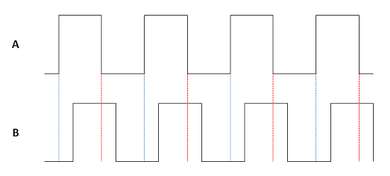
The two waves are out of phase by 90° (not quite right in my diagram, I know). The dotted red line shows us that, when turning clockwise, and the signal from A changes from high to low, the B signal will be a high. When turning anticlockwise, when A changes from high to low, there is a dotted blue line showing us that the B signal will be low.
So, what matters to us is the change in output on pin A. When that occurs, we read the signal on pin B and can use that to determine the direction in which the encoder was rotated.
You Will Need
- Rotary Encoder
- Jumper Wires
Like most digital inputs, we need pullup resistors for the A and B pins of the encoder. The Arduino's internal pullups will be used for this project.
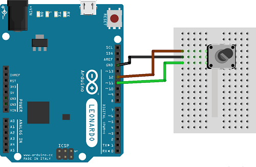
Making The Circuit
The simplest bit of wiring you could do - pin C goes to GND. Pin A is connected to pin 12 and Pin B to pin 11 on the Arduino.
Programming The Arduino
The sketch takes readings from the rotary encoder and outputs the value to the Serial port when there is a change in the reading. Readings are taken every 5 milliseconds. This gives enough time to avoid any false readings. When I use this sketch, I can get all of the values in the range -12 to 12. In fact, this range was deliberately chosen because the rotary encoder I was using has 24 positions - it takes one 360° turn to cover the whole range of my counter.
// Setting up the counter

int reading = 0;

int lowest = -12;

int highest = 12;

int changeamnt = 1;


// Timing for polling the encoder

unsigned long currentTime;

unsigned long lastTime;


// Pin definitions

const int pinA = 12;

const int pinB = 11;


// Storing the readings


boolean encA;

boolean encB;

boolean lastA = false;


void setup()  {

  // set the two pins as inputs with internal pullups

  pinMode(pinA, INPUT_PULLUP);

  pinMode(pinB, INPUT_PULLUP);

  // Set up the timing of the polling

  currentTime = millis();

  lastTime = currentTime;

  // Start the serial monitor for debugging

  Serial.begin(9600);

}


void loop()

{

  // Read elapsed time

  currentTime = millis();

  // Check if it's time to read

  if(currentTime >= (lastTime + 5))

  {

    // read the two pins

    encA = digitalRead(pinA);

    encB = digitalRead(pinB);

    // check if A has gone from high to low

    if ((!encA) && (lastA))

    {

      // check if B is high

      if (encB)

      {

        // clockwise

        if (reading + changeamnt <= highest)

        {

          reading = reading + changeamnt;

        }

      }

      else

      {

        // anti-clockwise

        if (reading - changeamnt >= lowest)

        {

          reading = reading - changeamnt;

        }

      }

      // Output reading for debugging

      Serial.println(reading);

    }

    // store reading of A and millis for next loop

    lastA = encA;

    lastTime = currentTime;


  }


}
Challenges
Clearly, changing the counter is a good first step. If you can adapt this code to change the way the counter works, then you can use the value of the reading for some other purpose - like fading an LED.
A more interesting project might be to work only with the changes in value. Instead of keeping track of a counter, do something on each change. For example, you could send a left or right keystroke each time the encoder was turned.