Other
Arduino - LED Projects
Arduino - Buzzer Projects
Arduino - Midi Projects
Arduino - Microview
Arduino - Other Projects
Arduino - Visual Basic.NET
Arduino - Tim's Projects
Arduino - Links
![]()


LolShield Clock
Introduction
The 'Lol' in 'LolShield' stands for 'Lots of LEDs'. It's a shield with 126 charlieplexed LEDs laid out in a 14x9 grid. It was designed by blogger and open source hacker Jimmie Rodgers. The design process, and a lot more, can be found by following the link to his blog.
The Jimmie Rodgers LolShield comes as a kit of parts and is sold widely. A ready-built shield with surface mount LEDs is also for sale. The two shields work in the same way. The main difference is that the through-hole LEDs are closer together and work better when used as pixels to display images and animations. Both the original and cloned shields are generally cheaper than the average Arduino shield.
The shield uses digital pins 2 to 13 to drive the matrix. Pins 0 and 1 are used by the arduino for communication (uploading sketches, serial communication) and so are not used. All of the analog pins remain free (which for the UNO also means that the I2C pins are free). The shields have solder holes for adding connections or headers to the analog pins and the power pins. There is a well-developed library with some interesting examples, including grid-based games and animations.
Since the shield uses charlieplexing, we still end up with a low-power project, despite the number of LEDs. The library is sufficiently well written to provide decent brightness on the LEDs and easy ways to manipulate the state of individual LEDs. The built-in LED and resistor on pin 13 can be an issue for the perfectionist. If you were using the shield in a finished project, you'd disconnect these or build your arduino from scratch.
This project is the result of a first play with the shield. The idea is to use an RTC and display the time using the LEDs on the shield.
You Will Need
- 1 x LOLShield
- DS1307 Breakout Board & RTC
- Jumpers
Making The Circuit
Once the shield is connected, there's only one more component, the RTC. The RTC uses the I2C interface. On the Leonardo, that means pins 2 and 3, already used by the shield. This project needs an UNO or MEGA, or any Arduino with a standard shield footprint and I2C on pins other than those take by the shield. If you have a pre-soldered shield and want to avoid soldering headers to the board, the MEGA is your only option. The RTC is low power and you can drive digital pins high and low to make alternative power pins (which the shield covers).
On the UNO, connect up the labelled pins of the RTC to A4 and A5 (I2C pins) and the 5V and GND.
Programming The Arduino
You need a couple of libraries for this. You need the RTCLib for the DS1307 or a different one if you are using another RTC. You also need the LolShield libaries, which you can download from here.
Planning The Display
Before writing any code, you need to get your head around how the time is to be displayed. The following image shows where the digits of the time will fit onto the grid,
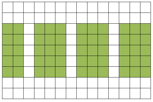
Our digits will be displayed on a 3x5 grid. The exception is the first digit. If we use a 12 hour clock and the hour is 9 or less, then no first digit needs to be displayed, if the hour is 10 or more, we only need to display a 1. That method just about allows us to fit in the digits.
The Font
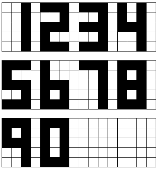
To display the time, we need to design a basic 3x5 font for the digits. The following image shows the planning for that,
Font Data
We need a handy way to store the details of our font. If we take the 0 digit and, using 1 for on, 0 for off, the first row of the digit is 1,1,1. The second row is 1,0,1 and so on. The digits are stored in order from 0-9, that way the index of the array's first dimenion will match the digit being displayed.
Final Code
#include <Wire.h>

#include "RTClib.h"

#include <avr/pgmspace.h>

#include <Charliplexing.h>

int digits[][15] = {

  {1,1,1,1,0,1,1,0,1,1,0,1,1,1,1}

  ,{0,0,1,0,0,1,0,0,1,0,0,1,0,0,1}

  ,{1,1,1,0,0,1,1,1,1,1,0,0,1,1,1}

  ,{1,1,1,0,0,1,1,1,1,0,0,1,1,1,1}

  ,{1,0,1,1,0,1,1,1,1,0,0,1,0,0,1}

  ,{1,1,1,1,0,0,1,1,1,0,0,1,1,1,1}

  ,{1,0,0,1,0,0,1,1,1,1,0,1,1,1,1}

  ,{1,1,1,0,0,1,0,0,1,0,0,1,0,0,1}

  ,{1,1,1,1,0,1,1,1,1,1,0,1,1,1,1}

  ,{1,1,1,1,0,1,1,1,1,0,0,1,0,0,1}

};


RTC_DS1307 RTC;


void setup () {

  Serial.begin(57600);

  Wire.begin();

  RTC.begin();

  if (! RTC.isrunning()) {

    Serial.println("RTC is NOT running!");

    // following line sets the RTC to the date & time this sketch was compiled

    RTC.adjust(DateTime(__DATE__, __TIME__));

  }

  LedSign::Init(DOUBLE_BUFFER);

}


void loop () {


  DateTime now = RTC.now();

  Serial.print(now.day(), DEC);

  Serial.print('/');

  Serial.print(now.month(), DEC);

  Serial.print('/');

  Serial.print(now.year(), DEC);

  Serial.print(' ');

  Serial.print(now.hour(), DEC);

  Serial.print(':');

  Serial.print(now.minute(), DEC);

  Serial.print(':');

  Serial.print(now.second(), DEC);

  Serial.println();

  int h = now.hour();

  if (h>12)

  {

    h=h-12;

  }

  // first digit of hours

  if (h>9)

  {

    for (int y=2;y<7;y++)

    {

      LedSign::Set(1,y,1);

    }

  }

  // second digit of hours

  for (int i=0;i<15;i++)

  {

    LedSign::Set((i % 3)+3,(i/3)+2,digits[h%10][i]);

  }

  // first digit of minutes

  for (int i=0;i<15;i++)

  {

    LedSign::Set((i % 3)+7,(i/3)+2,digits[now.minute()/10][i]);

  }

  //second digit of minutes

  for (int i=0;i<15;i++)

  {

    LedSign::Set((i % 3)+11,(i/3)+2,digits[now.minute()%10][i]);

  }

  LedSign::Flip();

  delay(1000);

}
There are several key parts to the sketch. We initialise the display in the setup() procedure. The display is double-buffered. That means that when you clear the display, you are clearing its buffer, not the screen. This happens before we refresh the display. Once all of the pixels that need to be switched on are set, we 'flip' the display so that the buffer is shown.
The calculation of the x and y coordinates is interesting here. A for loop counts the 15 steps that correspond to the 15 pixels of each digit. The remainder when the counter is divided by 3 provides the x offset. When the counter is divided by 3 and the decimal part of the answer disregarded, you get the y offset.
| i | 0 | 1 | 2 | 3 | 4 | 5 | 6 | 7 | 8 | 9 | 10 | 11 | 12 | 13 | 14 |
|---|---|---|---|---|---|---|---|---|---|---|---|---|---|---|---|
| i mod 3 | 0 | 1 | 2 | 0 | 1 | 2 | 0 | 1 | 2 | 0 | 1 | 2 | 0 | 1 | 2 |
| i div 3 | 0 | 0 | 0 | 1 | 1 | 1 | 2 | 2 | 2 | 3 | 3 | 3 | 4 | 4 | 4 |
Challenges
This page describes a quick and easy way to get the time shown on the shield. There are other, and better, ways to do that.
Better Font
The font used here was knocked up very quickly. There are some issues. All of the digits need 3 columns except for the 1. That is fine for the first digit, but looks odd when it's the last digit. If the first digit in the display is a 1, this 1 is not drawn from the array. If you change the design of the 1 digit, you'd need to look at how this first digit was coded.
Using a 3x7 grid would make taller figures and should still work.
Different Orientation
If you display the images on the shield in 'portrait orientation', you can fit 2 hour digits above 2 minute digits and still have space for a flashing colon.
More Inventive
You have 126 LEDs at your disposal. You could think of all sorts of interesting ways to represent the time and date.
People expect clocks to have movement. Most clocks have some visible moving elements. On an analog clock it's the second hand, or the ticking that reminds us that the time we are reading is only accurate for that precise moment. Even digital clocks tend to flash the colon once a second.
You could think of some cool ways to present the time or simply add a suitable animation.
More Functionality
Using an UNO, you still have A0-A3 unused. You could get a couple of sensors and a few buttons into the circuit. If you added a temperature or humidity sensor (DHT 11 gives you humidity and temperature), you could make that something that can be displayed on your grid when a button is pressed.
With a button and a rotary encoder, you have a nice pair of tools for setting the time on the display.
On the UNO, the analog pins cannot be used for hardware PWM. If you muck about with resistors, you could still make a buzzer perform an approximation of ticking. On a MEGA, you still have access to PWM pins 44-46. These could be used to play some alarm-like noises.
Depending on the board you are using, you may have the right pins left over for SoftwareSerial. This would allow you to do things like send MIDI messages or communicate with components that have their own microcontroller.