Other
Arduino - LED Projects
Arduino - Buzzer Projects
Arduino - Midi Projects
Arduino - Microview
Arduino - Other Projects
Arduino - Visual Basic.NET
Arduino - Tim's Projects
Arduino - Links
![]()


VB - LolShield Assistant
Introduction
The 'Lol' in 'LolShield' stands for 'Lots of LEDs'. It's a shield with 126 charlieplexed LEDs laid out in a 14x9 grid. It was designed by blogger and open source hacker Jimmie Rodgers. The design process, and a lot more, can be found by following the link to his blog.
The Jimmie Rodgers LolShield comes as a kit of parts and is sold widely. A ready-built shield with surface mount LEDs is also for sale. The two shields work in the same way. The main difference is that the through-hole LEDs are closer together and work better when used as pixels to display images and animations. Both the original and cloned shields are generally cheaper than the average Arduino shield.
The shield uses digital pins 2 to 13 to drive the matrix. Pins 0 and 1 are used by the arduino for communication (uploading sketches, serial communication) and so are not used. All of the analog pins remain free (which for the UNO also means that the I2C pins are free). The shields have solder holes for adding connections or headers to the analog pins and the power pins. There is a well-developed library with some interesting examples, including grid-based games and animations.
Since the shield uses charlieplexing, we still end up with a low-power project, despite the number of LEDs. The library is sufficiently well written to provide decent brightness on the LEDs and easy ways to manipulate the state of individual LEDs. The built-in LED and resistor on pin 13 can be an issue for the perfectionist. If you were using the shield in a finished project, you'd disconnect these or build your arduino from scratch.
The number of LEDs on the LolShield makes it usable for displaying very small bitmaps and simple frame-by-frame animation. In the LolShield clock project, we were turning LEDs on and off one at a time, using an array to define the digits we wanted to display. In this project we need a data structure to store each frame. We use a binary number (14 bit) to describe the pattern of on and off LEDs on each row of the display. Our VB program will help us to form these numbers from 'drawings' that the user makes using the mouse.
The application will look something like this,
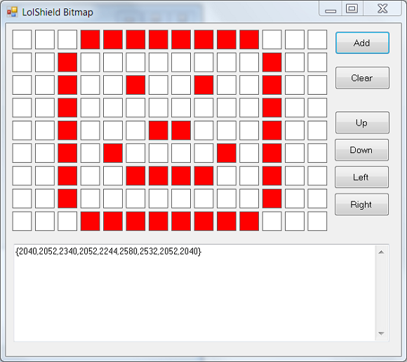
The user can click on the squares to turn them red or white. Red squares represent the LEDs that are on. When the 'Add' button is pressed, the binary numbers for the display are added to the textbox as an array of integers.
Step 1 - Start A New Project
You need a new Windows Forms project. The main form will need to be around 630 x 560 pixels. For now, you don't need to add any controls to the form, but you may as well change the Text property to something meaningful.
Step 2 - Making The Clickable PictureBoxes
Choose to View Code and add the following global variable to the code window,
Dim picPixel(13, 9) As PictureBox
This 2-dimensional array will give us a way of manipulating and reading information from the pictureboxes. Go back to the Designer view and double click on the form. This should bring up the event handler for the Form's load event. The following code generates the boxes and adds a click event for them. The code to process that click event is also shown below,
Private Sub Form1_Load(sender As Object, e As EventArgs) Handles MyBase.Load

   For y As Integer = 0 To 8

      For x As Integer = 0 To 13

         picPixel(x, y) = New PictureBox()

         With picPixel(x, y)

            .Size = New Size(30, 30)

            .BorderStyle = BorderStyle.FixedSingle

            .BackColor = Color.White

            .Location = New Point(10 + (x * 35), 10 + (y * 35))

         End With

         AddHandler picPixel(x, y).Click, New EventHandler(AddressOf PictureBox_Click)

         Me.Controls.Add(picPixel(x, y))

      Next

   Next

End Sub


Sub PictureBox_Click(sender As Object, e As MouseEventArgs)

   Dim p As PictureBox = sender

   If p.BackColor = Color.White Then

      p.BackColor = Color.Red

   Else

      p.BackColor = Color.White

   End If

End Sub
This is a fairly standard way of generating a large number of controls on a form at runtime. The difficulty you have, if any, is in working out the location of each item. Fortunately, our items are laid out in a grid and there is a mathematical relationship between the array subscripts and the location of the item on the form.
You can test the program at this point. Clicking on the boxes should toggle the colour of the background between red and white.
Step 3 - Making The Binary Numbers
Before dealing with the button, we will add a function to convert the picturebox backgrounds into binary numbers. The following function does this and returns the information as a string.
Function PicturesToString() As String

   Dim strO As String = "{"

   Dim tmpInt As Integer = 0

   For y As Integer = 0 To 8

      tmpInt = 0

      For x As Integer = 0 To 13

         If picPixel(x, y).BackColor = Color.Red Then

            tmpInt += Math.Pow(2, x)

         End If

      Next

      strO &= Trim(Str(tmpInt))

      If y < 8 Then

         strO &= ","

      End If

   Next

   strO &= "}"

   Return strO

End Function
Add a button to the form. Change its name to btnMake and choose some suitable text. Add a textbox called txtOutput to the form and make sure it is Multiline and set to show a vertical scrollbar. Double click on the button to bring up its event handler and amend the code as follows,
Private Sub btnMake_Click(sender As Object, e As EventArgs) Handles btnMake.Click

   If txtOutput.Text <> "" Then

      txtOutput.Text &= "," & vbNewLine & PicturesToString()

   Else

      txtOutput.Text = PicturesToString()

   End If

End Sub
Step 4 - Using The Program
Start by making a simple animation. Draw a pattern and press the button to make the numbers. Change it slightly and press the button again. Keep doing this a few times until you have a handful of frames. In the screenshot below, you can see the result of doing this. I've just moved a single dot around each time a frame changes.
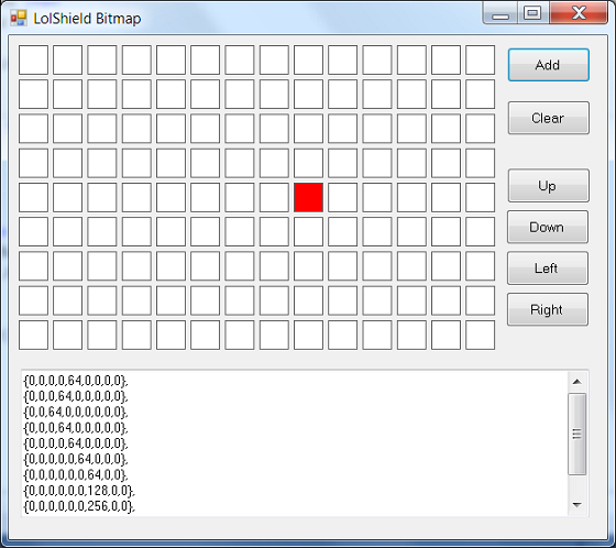
The numbers from the textbox have been copied and pasted into the code below, into the defintition of the bmp variable. In the loop, the number 11 is used because we have 11 frames (count them). Change this number to the number of frames that you have and upload.
#include <Charliplexing.h>

byte line = 0;

int bmp[][9] = {

{0,0,0,0,64,0,0,0,0},

{0,0,0,64,0,0,0,0,0},

{0,0,64,0,0,0,0,0,0},

{0,0,0,64,0,0,0,0,0},

{0,0,0,0,64,0,0,0,0},

{0,0,0,0,0,64,0,0,0},

{0,0,0,0,0,0,64,0,0},

{0,0,0,0,0,0,128,0,0},

{0,0,0,0,0,0,256,0,0},

{0,0,0,0,0,256,0,0,0},

{0,0,0,0,256,0,0,0,0}

};

void setup()

{

  LedSign::Init();

}


void loop()

{

  for (int j=0;j<11;j++)

  {

    for (int i =0;i<9;i++)

    {

      DisplayBitMap(bmp[j][i]);

    }

    delay(50);

  }

}


void DisplayBitMap(int lineint)

{

  for (byte led=0; led<14; ++led) {

    if (lineint & (1<<led)) {

      LedSign::Set(led, line, 1);

    }

    else {

      LedSign::Set(led, line, 0);

    }

  }

  line++;

  if(line >= 9) line = 0;

}
Challenges
Functionality Needed
In the screenshots of my program, you can see 5 buttons which have not been explained on this page. Their function is pretty obvious and useful to the animation process. Working out how to implement these features won't take too long and will add to the usability of your program.
Other straightforward tools to implement include reversing the image, mirroring horizontally or vertically, and adding or removing a border to the screen.
Going A Little Further
Rotating the image is a nice challenge. You have to make decisions about the loss of information when you do this on a non-square grid.
Being able to save the information you are creating would be worthwhile. It means storing the numeric information about each frame (not currently done in the program).
Even Better
The program could generate all of the code that you need for your animation. Arduino sketches are text files with a .ino extension. A sketch is expected to be in a folder with the same name (minus the extension). All of this could be generated from a VB program at the instigation of the user. The animation speed could also be set by the user and hard-coded into the sketch that is produced from the program.
Luxury Features
Currently, there is no way to keep track of each frame. Imagine being able to see a list of frames. Clicking on a frame title or number would display the pattern for that frame. Frames could then be edited, removed, re-ordered.
Instead of having a text list of frames, you could display 'thumbnails' of each frame in a storyboard-like layout like you would find in film-editing software. Clicking on a frame allows you to edit it. Drag and drop could be used for reordering.
Finally, consider the fact that this program needs a preview feature and implement that.