Other
Arduino - LED Projects
Arduino - Buzzer Projects
Arduino - Midi Projects
Arduino - Microview
Arduino - Other Projects
Arduino - Visual Basic.NET
Arduino - Tim's Projects
Arduino - Links
![]()


Charlieplexing LEDs
Introduction
This page has a longish explanation of the concept followed by an example project for you to make.
Charlieplexing
Multiplexing is the name given to the techniques used to reduce the number of pins required to drive a component. Charlieplexing is a multiplexing technique that takes advantage of the microcontroller's ability to puts digital pins into 3 states (high, low, input) in order to dramatically reduce the number of pins required to drive a given number of LEDs. The technique is named after its inventor, Charlie Allen, who proposed the technique in the mid 90's whilst working at Maxim Integrated Products.
In order to achieve this, the LEDs are connected in a specific matrix. The 2 x LED matrix looks like this,
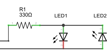
The 2 wires on the left of the diagram are each connected to a different digital pin on the Arduino. Clearly, with 2 pins and 2 LEDs, this configuration offers no savings. It does, however, help to illustrate the central principle behind the way that charlieplexing works. For LED 1 to be lit, the top wire needs to be HIGH and the bottom wire LOW. This would mean that LED 2 would be receiving a LOW at its anode and a HIGH at its cathode - so it would not be lit. To light LED 2, the top wire needs to be LOW and the bottom HIGH. This means that LED 1 is turned off. Current only flows the correct way through one of the diodes. The resistor is always in series with the LED that is lit.
Adding another digital pin, makes the circuit below - LEDs shown as plain diodes,
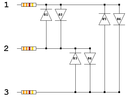
For this matrix, we need to use that third logic state, INPUT. To light LED 1, there needs to be a HIGH signal on wire B and a LOW signal on wire A. Wire C needs to be disconnected in some fashion in order for that circuit to complete without lighting any of the other LEDs. This is done by setting the pin to an INPUT. This puts it into a high impedance state and effectively disconnects it from the circuit. In the high impedance state, the pin is neither high, nor low and little or no current is being passed to the circuit from it. The full table of pin settings for each LED are as follows,
| LED | Pin A | Pin B | Pin C |
|---|---|---|---|
| 1 | LOW | HIGH | INPUT |
| 2 | HIGH | LOW | INPUT |
| 3 | INPUT | HIGH | LOW |
| 4 | INPUT | LOW | HIGH |
| 5 | HIGH | INPUT | LOW |
| 6 | LOW | INPUT | HIGH |
In the schematic, the LEDs are shown in pairs. Each pair is connected to the same two pins. Pin A is connected to the cathode of LED 1 and the anode of LED 2, Pin B is connected to the anode of Pin A and the cathode of Pin B. Pin C is not connected to this pair so needs to be disconnected to light one of these two LEDs. LEDs 3 & 4 and 5 & 6 also form pairs in this way.
By increasing the number of digital pins from 2 to 3, we were able to add an extra 4 LEDs. The scaling up of the system is what matters and how that compares to traditional multiplexing.
Traditional Multiplexing
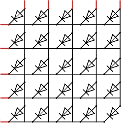
The diagram above shows 25 LEDs arranged in a 5x5 matrix. Each column connects the anodes of 5 LEDs together. Each row connects the cathodes of 5 LEDs together. You need a total of 10 pins to drive this matrix directly from a microcontroller. So we need 2 x n pins to drive n x n LEDs with the traditional multiplexed matrix.
In a charlieplexed matrix, n pins can control n x (n - 1) pins. The comparison between the two approaches is shown in the table below,
| Number Of Pins | LEDs Charlieplexed | LEDs Traditional |
|---|---|---|
| 1 | 0 | 0 |
| 2 | 2 | 1 |
| 3 | 6 | 1 |
| 4 | 12 | 4 |
| 5 | 20 | 4 |
| 6 | 30 | 9 |
| 7 | 42 | 9 |
| 8 | 56 | 16 |
| 9 | 72 | 16 |
| 10 | 90 | 25 |
| 11 | 110 | 25 |
| 12 | 132 | 36 |
| 13 | 156 | 36 |
| 14 | 182 | 49 |
| 15 | 210 | 49 |
| 16 | 240 | 64 |
See how quickly the number of LEDs scales up. Running a matrix takes a fair bit of current. In a charlieplexed matrix, there is only ever one LED on at any time.
Charlieplexing is ideal when you only need to light one LED at a time. You can give the appearance of having all of the LEDs lit by turning LEDs on and off very quickly. If the refresh rate is quick enough, say 50Hz (you redraw the pattern of on and off LEDs 50 times a second), then there is no visible flicker.
Setting a pin high and low very quickly changes its duty cycle. The duty cycle is the percentage of a time period for which a signal is high. The PWM that you use to make the fading LED works the same way. When you wrote a low number to the LED pin, the LED became less bright. The same happens here if the refresh rate isn't quick enough. One way to overcome this is to vary the resistor so that more current goes through the LED. At this point, the concept of peak current comes into play. This is often specified for an LED, exceed the figure and the LED is going to pop on you.
The major issue is timing. Any delays in your program mean that you are stuch with only one LED on at a time.
You Will Need
- 6 x LEDs
- 3 x 330 Ohm Resistors
- Jumper Wires
Making The Circuit
Lining up the LEDs nicely makes this a bit fiddly.
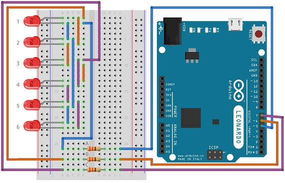
If you are having trouble setting up the layout here, then look again at the schematic below and follow the written wiring instructions. Wire colours are only mentioned to match the diagram.
Pin 3 (Blue Wires)
- Pin 3 to Resistor A
- Resistor A to cathode of LED 1 (short leg)
- Cathode of LED 1 to anode of LED 2
- Anode of LED 2 to cathode of LED 5
- Cathode of LED 5 to anode of LED 6
Pin 4 (Orange Wires)
- Pin 4 to Resistor B
- Resistor B to anode of LED 1
- Anode of LED 1 to cathode of LED 2
- Cathode of LED 2 to cathode of LED 3
- Cathode of LED 3 to anode of LED 4
Pin 5 (Purple Wires)
- Pin 5 to Resistor C
- Resistor C to anode of LED 3
- Anode of LED 3 to cathode of LED 4
- Cathode of LED 4 to anode of LED 5
- Anode of LED 5 to cathode of LED 6
Programming The Arduino
#define LED_A 3

#define LED_B 4

#define LED_C 5


void setup()

{

  pinMode(LED_A, INPUT);

  pinMode(LED_B, INPUT);

  pinMode(LED_C, INPUT);

}

void loop()

{

  // loop through one at a time

  for (int i=1;i<=6;i++)

  {

    light_led(i);

    delay(500);

  }


}

void reset_pins()

{

  pinMode(LED_A, INPUT);

  pinMode(LED_B, INPUT);

  pinMode(LED_C, INPUT);

  digitalWrite(LED_A, LOW);

  digitalWrite(LED_B, LOW);

  digitalWrite(LED_C, LOW);

}

void set_pins(int high_pin, int low_pin)

{

  reset_pins();


  // set the high and low pins to output

  pinMode(high_pin, OUTPUT);

  pinMode(low_pin, OUTPUT);


  // set logic as required

  digitalWrite(high_pin, HIGH);

  digitalWrite(low_pin, LOW);

}


void light_led(int led_num)

{


  switch (led_num)

  {

  case 1:

    set_pins(LED_B, LED_A);

    break;

  case 2:

    set_pins(LED_A, LED_B);

    break;

  case 3:

    set_pins(LED_C, LED_B);

    break;

  case 4:

    set_pins(LED_B, LED_C);

    break;

  case 5:

    set_pins(LED_C, LED_A);

    break;

  case 6:

    set_pins(LED_A, LED_C);

    break;

  }

}
Challenges
Nail The Programming
The sketch gives you what you need to turn lights on and off. A simple change to the sample sketch and you can make it so that all LEDs appear to be on at the same time. You should also add a procedure to make it appear like any combination of LEDs is on at the same time (the binary counter page might be useful).
Scale Up
The schematic for 4 digital pins, 12 LEDs is shown below,
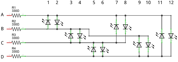
With an extra or using a full size breadboard, you can make this happen and keep the lovely straight column.
When it comes to the program, you will need to work out your logic table like the one in the introduction. Yours will have and extra column for the extra digital pin and 6 extra rows. For each LED the high and low pins are the ones that it is connected to - all of the others are set to be inputs.
The sample sketch is written like that for clarity. It's not scalable without major adjustment. One way to do this is to use an array to store the pin numbers like in the 4 LED binary counter.
The LEDs are grouped in pairs in the schematic. Notice that each pair requires high and low signals on the same 2 digital pins, inputs on all of the others. If you had an array for your pins, like,
int ledPin[] = {4,5,6,7};
You could then define an array of the combinations that need to be set when you turn on an LED. It isn't shown in full here so you can work it out yourself.
int charliePin[][] = {{ledPin[1],ledPin[0]},{ledPin[0],ledPin[1]},
{ledPin[2],ledPin[1]},{ledPin[1],ledPin[2]},...};
To turn on LED 2, you'd write,
set_pins(charliePin[1][0],charliePin[1][1]);
It is charliePin[1][?] and not charliePin[2][?] because the array starts at zero.Just subtract 1 from the LED number.
The reset procedure can be simplified. Use a for loop with the ledPin array to set all of the pins to inputs and low.
Timing
The timing issue can be solved. You'll need to do a bit of exploration on how to use timers and interrupts.
Making Some Stuff
If you made the 12 LED circuit, you could make a nice tune player where the lights followed the notes of the music, or use the LEDs as an indicator for a simple sequencer. With 12 buttons, or toggle buttons, or some DIP switches, you could set this up nicely. The buttons should switch the lights on and off. In each loop, play up to 12 tones of identical duration, depending on which LEDs were lit.
With 5 pins and a charlieplexed matrix, you would be able to make a workable Noughts & Crosses. You'd need 10 LEDs of one colour and 10 LEDs of another colour. One colour for each player. 18 of the LEDs used to make up a 3x3 grid pattern with one LED of each colour. The two spare ones are used to indicate which player is due to play or which player has won. Add a buzzer and 9 buttons laid out in the same grid. That takes 15 pins. The buzzer needs to be on a PWM pin. The others can be where you like, using analog pins if needed. Each grid position has a pair of LEDs. Match your layout up with the pairing principle from the schematic you find/work out for this. This would be a time-consuming but highly satisfying project to undertake. Setting up the breadboard would be victory enough, the programming would be a decent-sized project too.