Other
Arduino - LED Projects
Arduino - Buzzer Projects
Arduino - Midi Projects
Arduino - Microview
Arduino - Other Projects
Arduino - Visual Basic.NET
Arduino - Tim's Projects
Arduino - Links
![]()


4 LED Binary Counter
Introduction
To understand this project, you need a working knowledge of binary numbers. An explanation and some interactive tools can be found on this page.
We will be using the LEDs to indicate a 1 (on) or 0 (off) for the first 4 place values in the binary place value table. That means we can represent numbers from 0 to 15.
You Will Need
- 4 x LEDs
- 4 x 330 Ohm Resistors
- Jumper Wires
Making The Circuit
The diagram shows how the circuit should look.
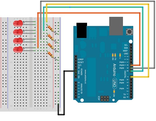
If you have been working through the projects in order, this is the circuit with the most wiring. With a bit of concentration, this one shouldn't be too much of a problem. Make sure that the longer lead (positive) of each LED is the one you connect to the Arduino pin and that the resistors connect the shorter lead (negative) to the GND rail.
To relate this to the binary place value table, turn the breadboard 90° in a clockwise direction. The LED at the top of the breadboard (connected to pin 7) becomes the rightmost bit (units). When this LED is on, that will mean a 1 in the units column. Moving leftwards, we have 2, 4 & 8 for our column headings.
Programming The Arduino - Checking Connections
Before doing anything too tricky, it makes sense to write a simple program to check that the connections are all correct. Here is the code to do that,
int ledPin[] = {7,8,9,10};


void setup()

{

  for (int i =0;i<4;i++)

  {

    pinMode(ledPin[i], OUTPUT);

  }

}


void loop()

{

  for (int i =0;i<4;i++)

  {

    digitalWrite(ledPin[i], HIGH);

  }

}
At the top of the program, we use an array to store the list of Arduino pins that we have connected to LEDs. In the setup, we use a for loop to set each of these pins to be output pins. In the main loop, we use another for loop to turn all of the pins on.
Run this code as it is and check that all of the LEDs turn on. Then change the HIGH to LOW to check that they all go off. If any of the LEDs don't light, check that they are correctly wired on the positive (longer) lead to an Arduino pin and that they have a resistor connecting the shorter (negative) lead to GND. If all of the connections seem correct, try swapping the LED for another one from the kit.
Programming The Arduino - Representing Binary Numbers
int ledPin[] = {7,8,9,10};


void setup()

{

  for (int i =0;i<4;i++)

  {

    pinMode(ledPin[i], OUTPUT);

  }

}


void loop()

{

  displayBinary(2);

}


void displayBinary(byte numToShow)

{

  for (int i =0;i<4;i++)

  {

    if (bitRead(numToShow, i)==1)

    {

      digitalWrite(ledPin[i], HIGH);

    }

    else

    {

      digitalWrite(ledPin[i], LOW);

    }

  }


}
In this code, we have a new procedure to display the binary number we want to show. Numbers in the programming language are actually stored in binary even when we set their values using denary. We can take advantage of that fact to avoid having to write code to do the conversion (although we could). In this code, a for loop is used to read the values of the first four bits of the number sent to the procedure. The bitRead function tells us whether there is a 1 or 0 at a given place value. If we find a 1, we turn that LED on, if we find a zero, we turn the LED for that position off.
Test this code with all of the different numbers from 0 to 15. You can also put in values up to 255. Numbers in this range need 8 place value columns to be represented. Since our code ignores the last 4 place values, the LEDs will only be on if that number has a 1 in one or more of the first 4 place value columns. All odd numbers will have the first place value lit up, all even numbers will mean it is not lit.
Programming The Arduino - Counting Upwards
This code makes use of the displayBinary procedure we wrote to count upwards in binary. The delay between displaying each number allows us to see clearly how the change made to display the next number in the sequence.
int ledPin[] = {7,8,9,10};


void setup()

{

  for (int i =0;i<4;i++)

  {

    pinMode(ledPin[i], OUTPUT);

  }

}


void loop()

{

  for (byte counter =0;counter<=15; counter++)

  {

    displayBinary(counter);

    delay(500);

  }

}


void displayBinary(byte numToShow)

{

  for (int i =0;i<4;i++)

  {

    if (bitRead(numToShow, i)==1)

    {

      digitalWrite(ledPin[i], HIGH);

    }

    else

    {

      digitalWrite(ledPin[i], LOW);

    }

  }


}
Challenge
Find out how to make the loop go backwards from 15 to 0 and make the circuit show you the numbers that way.
Programming The Arduino - Patterns
Now that we can represent any number from 0 - 15 in binary, we can take advantage of that fact to turn any number of the lights on using only a single number as a reference. In the following code, an array of numbers is used to create a looping pattern where the light seems to bounce from side to side.
int ledPin[] = {7,8,9,10};


void setup()

{

  for (int i =0;i<4;i++)

  {

    pinMode(ledPin[i], OUTPUT);

  }

}


void loop()

{

  byte nums[] = {0, 1, 3, 6, 4, 12, 8, 12, 4, 6, 3, 1, 0};

  for (byte i = 0; i<13;i++)

  {

    displayBinary(nums[i]);

    delay(25);

  }

}


void displayBinary(byte numToShow)

{

  for (int i =0;i<4;i++)

  {

    if (bitRead(numToShow, i)==1)

    {

      digitalWrite(ledPin[i], HIGH);

    }

    else

    {

      digitalWrite(ledPin[i], LOW);

    }

  }

}
Challenges
- Adapt the circuit to include more LEDs. You can just about fit 8 LEDs vertically on one side of a half breadboard. Adapt the code so that 8 place values are used. The side-to-side pattern looks more impressive with more LEDs.
- Write code to light up each LED in turn. Use the same approach as for making the patterns. Each number in the array will be the place value of the column the LED represents.
- Try out this approach to make some other patterns. For example, the LEDs in odd or even positions.