Other
Arduino - LED Projects
Arduino - Buzzer Projects
Arduino - Midi Projects
Arduino - Microview
Arduino - Other Projects
Arduino - Visual Basic.NET
Arduino - Tim's Projects
Arduino - Links
![]()


Robot Control
Introduction
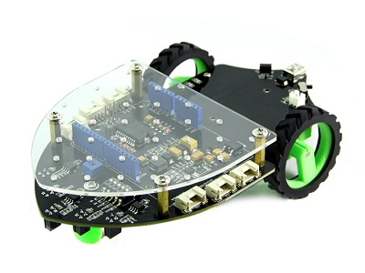
This page is concerned with different approaches to controlling a wheeled robot. The sketches on this page were made using the Seeedstudio Shieldbot (shown below). This is an Arduino shield with motors and wheels to which you can attach an Arduino Uno.
The Wiki for the Shieldbot can be found at http://www.seeedstudio.com/wiki/Shield_Bot_V1.0. There is a link on that page to the Arduino library for the shield. There are also explanations of two of the examples that come with the library. The first of these demonstrates how to make the robot follow a black line using its infra-red line finders. The second demonstrates how to make the robot move.
Although it doesn't state it on the page, digital pins 5 -10 (inclusive) are used to control the motors. Don't attach any devices to these pins. Also, when the line-following functionality is being used, all of the analog pins are out of action.
With all this work already done for us, we need to think now about how we might control the robot for our own purposes. In essence, this means deciding on the inputs that will determine how the robot should move. There are many different ways we can do this.
Method 1 - Ultrasound
We can program the robot to move until it senses an object in its path. At that point we can make it turn in a predetermined or even random fashion. This makes for a robot that is autonomous, moving without any need for user interaction.
This sketch is based on the SRF05 ultrasound sensor. The first step is to make sure that you can get reasonable readings from the sensor. You should be able to get fairly accurate distance measurements in the range 3cm to 4m. We probably need to stop the robot around 30cm from an obstacle to ensure that there is sufficient space to make it turn. The circuit layout is shown on a breadboard below,
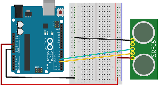
Basic code for getting the distance is shown below,
#define ECHOPIN 2

#define TRIGPIN 3


void setup() {

  pinMode(ECHOPIN, INPUT);

  pinMode(TRIGPIN, OUTPUT);

  Serial.begin(9600);

}


void loop() {

  digitalWrite(TRIGPIN, LOW);

  delayMicroseconds(2);

  digitalWrite(TRIGPIN, HIGH);

  delayMicroseconds(10);

  digitalWrite(TRIGPIN, LOW);

  int distance = pulseIn(ECHOPIN, HIGH);

  distance= distance/58;

  Serial.println(distance);

  delay(50);

}
Similar
Using an infrared sensor, you can achieve the same effect. An alternative is to use light sensors. If you place them pointing forwards at angles like two antennae, you can take a reading from each and make the robot move in the direction where it sense the most light. This would also have the benefit that of allowing you to use a light source (like a torch) to attract the robot in a particular direction.
Once you are happy that the distance measurements are usable, you need to plan how the robot will move. Use the reference on the shieldbot wiki page to help you decide how to move in response to sensor readings.
Method 2 - Infrared Remote Control
This sketch uses the parts from the DFrobot infrared kit (shown below). The kit consists of an infrared sensor and a standard remote control.
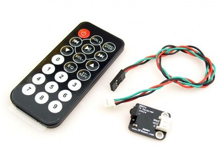
The following is a very basic sketch using the stock code for the IR kit. I have not made the best choices for movement here and this doesn't give you a sense of complete control. Some of this is down to the way you take a reading from the sensor, some of it is caused by the choices made about how to move in response to the readings.
The data pin for the sensor is connected to digital pin 11.
#include <Shieldbot.h>


Shieldbot shieldbot = Shieldbot();


#define IR_BIT_LENGTH 32    // number of bits sent by IR remote

#define FirstLastBit 15     // divide 32 bits into two 15 bit chunks for integer variables. Ignore center two bits. they are all the same.

#define BIT_1 1500          // Binary 1 threshold (Microseconds)

#define BIT_0 450           // Binary 0 threshold (Microseconds)

#define BIT_START 4000      // Start bit threshold (Microseconds)


#define IR_PIN 11            // IR Sensor pin


int debug = 0;              // flag as 1 to output raw IR pulse data stream length in microseconds

int output_verify = 0;      // flag as 1 to print decoded verification integers. same number for all buttons

int output_key = 0;         // flag as 1 to print decoded key integers

int remote_verify = 16128;  // verifies first bits are 11111100000000 different remotes may have different start codes


void setup(){

  Serial.begin(9600);

  shieldbot.setMaxSpeed(255);//255 is max

  pinMode(IR_PIN, INPUT);


}


void loop(){


  int key = get_ir_key();

  do_response(key);


}


void leftSquare(){

  shieldbot.drive(127,127); //straight forward

  delay(750);

  shieldbot.drive(-128,127);   //turn left on a dime

  delay(325);  //to turn 90, it depends on surface, ~450 on hard floors, ~325 on carpet

}


void forwards(){

  shieldbot.drive(127,127);

}

void backwards(){

  shieldbot.drive(-127,-127);

}

void leftCircle(){

  shieldbot.drive(25,127);

}


void rightCircle(){

  shieldbot.drive(127,25);

}


void whoa()

{

  shieldbot.drive(0,0);

}


int get_ir_key()

{

  int pulse[IR_BIT_LENGTH];

  int bits[IR_BIT_LENGTH];


  do {

  } //Wait for a start bit

  while(pulseIn(IR_PIN, HIGH) < BIT_START);


  read_pulse(pulse);

  pulse_to_bits(pulse, bits);

  RemoteVerify(bits);

  return bits_to_int(bits);

}


/*

  use pulseIn to receive IR pulses from the remote.

 Record the length of these pulses (in ms) in an array

 */


void read_pulse(int pulse[])

{

  for (int i = 0; i < IR_BIT_LENGTH; i++)

  {

    pulse[i] = pulseIn(IR_PIN, HIGH);

  }

}


/*

  IR pulses encode binary "0" as a short pulse, and binary "1"

 as a long pulse.  Given an array containing pulse lengths,

 convert this to an array containing binary values

 */


void pulse_to_bits(int pulse[], int bits[])

{

  if (debug) {

    Serial.println("-----");

  }

  for(int i = 0; i < IR_BIT_LENGTH; i++)

  {

    if (debug) {

      Serial.println(pulse[i]);

    }

    if(pulse[i] > BIT_1) //is it a 1?

    {

      bits[i] = 1;

    }

    else if(pulse[i] > BIT_0) //is it a 0?

    {

      bits[i] = 0;

    }

    else //data is invalid...

    {

      Serial.println("Error");

    }

  }

}


/*

  check returns proper first 14 check bits

 */


void RemoteVerify(int bits[])

{

  int result = 0;

  int seed = 1;


  //Convert bits to integer

  for(int i = 0 ; i < (FirstLastBit) ; i++)

  {

    if(bits[i] == 1)

    {

      result += seed;

    }


    seed *= 2;

  }

  if (output_verify)

  {

    Serial.print("Remote ");

    Serial.print(result);

    Serial.println(" verification code");

  }

  if (remote_verify != result) {

    delay (60);

    get_ir_key();

  } //verify first group of bits. delay for data stream to end, then try again.

}


/*

  convert an array of binary values to a single base-10 integer

 */


int bits_to_int(int bits[])

{

  int result = 0;

  int seed = 1;


  //Convert bits to integer

  for(int i = (IR_BIT_LENGTH-FirstLastBit) ; i < IR_BIT_LENGTH ; i++)

  {

    if(bits[i] == 1)

    {

      result += seed;

    }

    seed *= 2;

  }

  return result;

}


/*

 respond to specific remote-control keys with different behaviors

 */


void do_response(int key)

{

  delay(130);                  // 2 cycle delay to cancel duplicate keypresses

  if (output_key)

  {

    Serial.print("Key ");

    Serial.println(key);

  }


  switch (key)

  {

  case 32640:  // turns on UUT power

    Serial.println("POWER");

    break;


  case 32385:  // FUNC/STOP turns off UUT power

    Serial.println("FUNC/STOP");

    break;


  case 32130:  // |<< ReTest failed Test

    Serial.println("|<<");

    leftCircle();

    break;


  case 32002:  // >|| Test

    Serial.println(">||");

    whoa();

    break;


  case 31875:  // >>| perform selected test number

    Serial.println(">>|");

    rightCircle();

    break;


  case 32512:  // VOL+ turns on individual test beeper

    Serial.println("VOL+");

    forwards();

    break;


  case 31492:  // VOL- turns off individual test beeper

    Serial.println("VOL-");

    backwards();

    break;


  case 31620:  // v scroll down tests

    Serial.println("v");

    break;


  case 31365:  // ^ scroll up tests

    Serial.println("^");

    break;


  case 30982:  // EQ negative tests internal setup

    Serial.println("EQ");

    leftSquare();

    break;


  case 30855:  // ST/REPT Positive tests Select Test and Repeat Test

    Serial.println("ST/REPT");

    break;


  case 31110:  // 0

    Serial.println("0");

    break;


  case 30600:  // 1

    Serial.println("1");

    break;


  case 30472:  // 2

    Serial.println("2");

    break;


  case 30345:  // 3

    Serial.println("3");

    break;


  case 30090:  // 4

    Serial.println("4");

    break;


  case 29962:  // 5

    Serial.println("5");

    break;


  case 29835:  // 6

    Serial.println("6");

    break;


  case 29580:  // 7

    Serial.println("7");

    break;


  case 29452:  // 8

    Serial.println("8");

    break;


  case 29325:  // 9

    Serial.println("9");

    break;


  default:

    {

      Serial.print("Key ");

      Serial.print(key);

      Serial.println(" not programmed");

    }

    break;

  }

}
Method 3 - Playstation Controller
The most intuitive way to control the robot is with a game controller. A PS3 controller has 2 analog joysticks, a pressure-sensitive D-pad, 7 buttons on the top and 4 shoulder/trigger buttons. The extra inputs can be used for all sorts of interesting additions to the robot or the code.
A PS3 controller connects to a PC or PS3 using either USB or bluetooth protocols. This example is based on the USB method and requires a USB Host Controller. For this project, I used the one made by Hobbytronics, with the PS3 firmware option selected.
For the controller, I chose a third party wireless controller. I got the Speedlink Strike Fx. In most respects, this controller is inferior to a Sony version. The main issue is the lack of a genuinely full range of values from the analog switches.I also found issues with the rumble - including not being able to stop it rumbling if I connected in certain ways. However, there are good reasons for choosing this one. The main reason is for the wireless aspect. A genuine controller uses different protocols for its bluetooth and USB connection modes. A Sony version would have to have been connected via USB - not great for a robot. The other issue is that I didn't want the Arduino to have to provide the power for the controller. The Speedlink controller works very well in this sketch.
You connect the USB host board to the Arduino via I2C. Once you have connected 5V and GND, the SDA and SCL pins of the USB host need to be connected to analog pins 4 and 5 respectively. Then put the receiver dongle for the controller in the USB socket on the USB host board.
I used the D-pad for control. Buttons have to be held down for movement. Much of the code in the sketch below is taken from the hobbytronics library. I have removed the rumble code. In the setup, you'll notice that the LEDs on the controller are turned on in sequence. This seemed to prevent the controller from rumbling constantly.
#include <Wire.h>

#include <Shieldbot.h>


#define  I2C_ADDRESS 41      // I2C Address of USB Host

#define  PS3_DATA_SIZE 35


typedef struct ps3_data {

  unsigned char joy_left_x;

  unsigned char joy_left_y;

  unsigned char joy_right_x;

  unsigned char joy_right_y;

  unsigned char accel_x;

  unsigned char accel_y;

  unsigned char press_up;

  unsigned char press_right;

  unsigned char press_down;

  unsigned char press_left;

  unsigned char press_lb;

  unsigned char press_rb;

  unsigned char press_lt;

  unsigned char press_rt;

  unsigned char press_triangle;

  unsigned char press_circle;

  unsigned char press_x;

  unsigned char press_square;

  unsigned char btn_left;

  unsigned char btn_down;

  unsigned char btn_right;

  unsigned char btn_up;

  unsigned char btn_start;

  unsigned char btn_joy_right;

  unsigned char btn_joy_left;

  unsigned char btn_select;

  unsigned char btn_square;

  unsigned char btn_x;

  unsigned char btn_circle;

  unsigned char btn_triangle;

  unsigned char btn_rt;

  unsigned char btn_lt;

  unsigned char btn_rb;

  unsigned char btn_lb;

  unsigned char btn_ps3;

}

;


ps3_data ps3;

Shieldbot shieldbot = Shieldbot();

unsigned long currentTime;

unsigned long ps3ReadTime;


void setup()

{

  Wire.begin();              // join i2c bus (address optional for master)


  //Start Serial port

  Serial.begin(9600);        // start serial for output

  // Cycle through the LEDS on the PS3 Controller

  delay(500);

  ps3_led(0x01);      // LED 1

  delay(500);

  ps3_led(0x02);      // LED 2

  delay(500);

  ps3_led(0x04);      // LED 3

  delay(500);

  ps3_led(0x08);      // LED 4


  delay(500);

  ps3_led(0x01);      // LED 1

  delay(500);

  shieldbot.setMaxSpeed(255);//255 is max


  currentTime = millis();

  ps3ReadTime = currentTime;

}


void loop()

{

  unsigned char i;

  currentTime = millis();

  if(currentTime >= (ps3ReadTime + 50)){

    // Get data from PS3 Controller every 50ms

    get_ps3();

    ps3ReadTime = currentTime;  // Updates ps3ReadTime

    adjustmotor();

  }

}


void adjustmotor()

{

  boolean up = (boolean)ps3.btn_up;

  boolean down = (boolean)ps3.btn_down;

  boolean left = (boolean)ps3.btn_left;

  boolean right = (boolean)ps3.btn_right;

  //  Serial.print(up);

  //  Serial.print(",");

  //  Serial.print(down);

  //  Serial.print(",");

  //  Serial.print(left);

  //  Serial.print(",");

  //  Serial.println(right);

  if (up&&left)

  {

    shieldbot.drive(25,127);

  }

  else if(up&&right)

  {

    shieldbot.drive(127,25);

  }

  else if(down&&right)

  {

    shieldbot.drive(-128,-25);

  }

  else if(down&&right)

  {

    shieldbot.drive(-25,-128);

  }

  else if(up)

  {

    shieldbot.drive(127,127);

  }

  else if(down)

  {

    shieldbot.drive(-128,-128);

  }

  else if(left)

  {

    shieldbot.drive(-128,127);

  }

  else if(right)

  {

    shieldbot.drive(127,-128);

  }

  else

  {

    shieldbot.drive(0,0);

  }

}


void get_ps3()

{

  // Get data from PS3 DualShock Controller

  // We only want single byte values (0 to 255)

  // We use a pointer to the ps3 struct we defined so we can populate the data in sequence


  uint8_t *ps3Ptr = (uint8_t *)&ps3;    // Create pointer to ps3 struct


  unsigned char data_values_rcvd=0;     // keep track of how many characters received

  Wire.beginTransmission(I2C_ADDRESS);  // transmit to device

  Wire.write(0);                        // Start receiving data from register 0

  Wire.endTransmission();               // end transmission


    // To retrieve all data we need 35 bytes, but restriction in Arduino means

  // we can only get 32 bytes at one go, so we split it into 2 reads


  Wire.requestFrom(I2C_ADDRESS, 28);    // request 28 bytes from PS3

  data_values_rcvd=0;

  while(Wire.available())

  {

    *ps3Ptr++ = Wire.read();            // receive a byte and increment pointer address

    data_values_rcvd++;

  }

  Wire.beginTransmission(I2C_ADDRESS);  // transmit to device

  Wire.write(28);                       // Start receiving data from register 28

  Wire.endTransmission();               // end transmission

  Wire.requestFrom(I2C_ADDRESS, PS3_DATA_SIZE-28);    // request outstanding bytes from PS3

  while(Wire.available())

  {

    *ps3Ptr++ = Wire.read();            // receive a byte and increment pointer address

    data_values_rcvd++;

  }

}


void ps3_led(unsigned char led)

{

  // Send led data to PS3 controller

  Wire.beginTransmission(I2C_ADDRESS);  // transmit to device

  Wire.write(51);                       // LED data register 51

  Wire.write(led);                      // LED Data

  Wire.endTransmission();               // end transmission

}