Other
Arduino - LED Projects
Arduino - Buzzer Projects
Arduino - Midi Projects
Arduino - Microview
Arduino - Other Projects
Arduino - Visual Basic.NET
Arduino - Tim's Projects
Arduino - Links
![]()


Digital Clock
Introduction
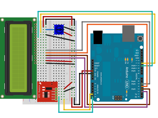
This project uses an LCD Display and a Real Time Clock module (RTC) to make a digital clock.
You Will Need
- 16 x 2 LCD Display (16 pin)
- DS1307 Breakout Board & RTC
- 10K Trimpot
- Jumper Wires
The LCD display is a standard Hitachi HD44780 compatible display for which can be controlled using the Arduino LiquidCrystal Library which is downloadable from the Arduino site. LCD displays cost between £5 and £10 depending on what you buy and where you buy it.
The RTC module used here is the Sparkfun module for the DS1307 RTC. These cost around £10. This can be controlled with a library from Adafruit that can be found at RTCLib.
There are alternatives to both of these components. These may be controlled in a different way and require different libraries to work properly.
Making The Circuit
Wire the circuit up according to the datasheet or tutorials for your components. You can usually find links to these on the retailer's web site.
Programming The Arduino
The first thing you need to do is set the time on the RTC. It will come with a coin cell battery and will store the time for the life of the battery. There is example code in the RTCLib to show how to do that. If you are using an alternative RTC module, use example code to set the time. You only need to do this once. With that done, the following code will show the time and date from the RTC on the LCD.
#include <Wire.h>

#include "RTClib.h"

#include <LiquidCrystal.h>


// initialize LCD

LiquidCrystal lcd(12, 11, 5, 4, 3, 2);


// initialize RTC

RTC_DS1307 RTC;


char months[][12] = {"No","Jan", "Feb", "Mar", "Apr", "May", "Jun", "Jul", "Aug", "Sep", "Oct", "Nov", "Dec"};

void setup() {

  // set up the LCD's number of columns and rows:

  lcd.begin(16, 2);

  Wire.begin();

  RTC.begin();

}


void loop() {

  // set the cursor to column 0, line 0

  lcd.setCursor(0, 0);

  DateTime now = RTC.now();

  int mins = now.minute();

  int secs = now.second();

  int hr = now.hour();

  lcd.print(hr);

  lcd.print(":");

  if (mins<10)

  {

    lcd.print(0);

  }

  lcd.print(mins);

  lcd.print(":");

  if (secs<10)

  {

    lcd.print(0);

  }

  lcd.print(secs);

  lcd.setCursor(0, 1);

  lcd.print(now.day());

  lcd.print(" ");

  lcd.print(months[now.month()]);

  lcd.print(" ");

  lcd.print(now.year());

  delay(100);

}
The first 3 lines import the libraries we need to use to control the components. Then the two components are initialised. The character array is used to convert month numbers into words.
There are lines in the setup() to start off the LCD, the RTC and the Wire library which is used for working with the RTC.
The rest of the code finds the date and time from the RTC and shows it on the LCD. There is some monkeying around to display leading zeroes but it's pretty basic.
Challenges
If you got this far, you may have realised that, even if you don't count the Arduino, this is a pretty costly digital clock. There is a lot more you could do with this though.
For a start, you could add a piezo element and get some 'chimes' and alarms going. A simple IF statement in the main loop would be enough to make that happen. The alarm could be a nasty noise or you could play around with some tunes.
Add some pushbuttons and you can make it so that the time, date and alarms could be set. You could allow for the time to be displayed in different formats or time zones. Binary or hex time would also be a nice alternative mode.
Add a temperature sensor and you can add thermometer functionality to your clock. Come to think of it, you could add any other sensors that you could lay your hands on.
For the ultimate clock, you need to think of what you might want the Arduino to do at various times of the day. Servos, motors, light sensors, Arduino shields and other components can be added to the circuit to suit whatever you can imagine the ultimate clock being able to do.