Other
Arduino - LED Projects
Arduino - Buzzer Projects
Arduino - Midi Projects
Arduino - Microview
Arduino - Other Projects
Arduino - Visual Basic.NET
Arduino - Tim's Projects
Arduino - Links
![]()


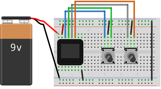
Microview Etch-A-Sketch
Introduction
This is a fairly simple project and a nice way to get some drawings on the Microview using some input components. This project uses the Microview but, clearly, you could use any graphical display with a more conventional Arduino. Rotary encoders are used for the input although these could be replaced with alternatives too.
You Will Need
- Microview
- Rotary Encoder x2
Making The Circuit
Programming The Arduino
The code here could be optimised - there is a fair bit of repetition. I've left it this way to make it easier to follow. The comments show you what is happening in each part. You might also find it useful to read the explanation of how to hook up a rotary encoder.
#include <MicroView.h>


// rotary encoder pins

const int pinA = 5;

const int pinB = 6;

const int pinC = 3;

const int pinD = 2;


// display dimensions

const int maxX = 63;

const int maxY = 47;


// starting coordinates for drawing

int readingX = 32;

int readingY = 24;


// keeping track of previous readings

boolean lastA = false;

boolean lastC = false;


// Timing for polling the encoders

unsigned long currentTime;

unsigned long lastTime;

const int pollFrequency = 10;


void setup() {

  // set the  pins as inputs with internal pullups

  pinMode(pinA, INPUT_PULLUP);

  pinMode(pinB, INPUT_PULLUP);

  pinMode(pinC, INPUT_PULLUP);

  pinMode(pinD, INPUT_PULLUP);

  // Set up the timing of the polling

  currentTime = millis();

  lastTime = currentTime;

  // set up the Microview

  uView.begin();

  uView.clear(ALL);

  uView.clear(PAGE);

  uView.pixel(readingX, readingY);

  uView.display();

}


void loop() {

  // Read elapsed time

  currentTime = millis();

  // Check if it's time to read

  if (currentTime >= (lastTime + pollFrequency))

  {

    // read the pins

    boolean encA = digitalRead(pinA);

    boolean encB = digitalRead(pinB);

    boolean encC = digitalRead(pinC);

    boolean encD = digitalRead(pinD);

    // check if A has gone from high to low

    if ((!encA) && (lastA))

    {

      // check if B is high

      if (encB)

      {

        // clockwise

        if (readingX + 1 <= maxX)

        {

          readingX = readingX + 1;

        }

      }

      else

      {

        // anti-clockwise

        if (readingX - 1 >= 0)

        {

          readingX = readingX - 1;

        }

      }

    }

    // check if C has gone from high to low

    if ((!encC) && (lastC))

    {

      // check if D is high

      if (encD)

      {

        // clockwise

        if (readingY + 1 <= maxY)

        {

          readingY = readingY + 1;

        }

      }

      else

      {

        // anti-clockwise

        if (readingY - 1 >= 0)

        {

          readingY = readingY - 1;

        }

      }

    }

    // store reading of A, C and millis for next loop

    lastA = encA;

    lastC = encC;

    lastTime = currentTime;

    // plot current pixel

    uView.pixel(readingX, readingY);

    uView.display();

  }

}
Challenges
This project is a really good starting point for exploring lots of other components and programming techniques. If you pick out from the sketch the key parts of the drawing logic, you can recreate this in lots of different ways. Which pixels get turned 'on' depends on 4 different boolean variables. The code could be reorganised so that you can more easily vary the components you use to get that information.
Clearing The Screen
You could clear the screen of the orignal toy by shaking it. Some way to replicate that feature would be a nice addition to the project. The simple thing to do would be to add a pushbutton or some other input component and make a call to the clear function when it is pressed. Alternatively, a tilt switch or accelerometer could be used to determine when to clear the screen.
Erasing
A mechanism for erasing parts of the drawing would be cool. Perhaps when you turn the dials with a button pressed, it removes pixels from the drawing rather than adding them.
Pen Lifting
The original toy made you do sketches that were fully connected. You could not lift the 'pen' from the screen. You could add an input to toggle a penup/pendown variable to determine whether or not to draw the pixel. To be able to do this, you need to have the equivalent of a cursor, some way for the user to know where the next drawing point is. Having the current point (readingX,readingY) blink on and off can do this. Bear in mind that the cursor is likely to move over parts of the image that you don't want to delete. If it blinks there, you'd need to have a way of knowing whether or not to redraw the pixel. You could solve this by keeping a copy of the screen in memory. Alternatively, you have a single global variable to store the state of the pixel when the cursor lands. Before moving the cursor, draw the current spot as it should be.
Alternative Inputs
The rotary encoders are a nice input for this project because there is no need to match the absolute rotation of the component to anything we are doing on screen. All we are reading is directional movement. The main part of the project is based on 4 HIGH/LOW readings. You could gather these from a lot of different components,
- Potentiometers - You need to make sure it's a linear potentiometer. You'd be matching analog voltages to screen coordinates and you have to work hard to replicate the precision that the rotary encoder offers.
- Pushbuttons - The simplest alternative. The buttons match up, down, left and right.
- Photoresistors - If you have 4 of them, you can use them like switches.
- Capacitive Touch - Either use a breakout board with a suitable integrated circuit or look into how you can DIY this. With some crocodile clips, you can use anything vaguely conductive as the touch switch.
- Joystick - A 4-way analog or digital joystick would work in this situation. With the analog joystick, you could speed and slow the movement. You could use the joystick on a Nunchuck too.
- Accelerometer - Tilting action...lovely. The accelerometer on the Nunchuck could be used.
- Infrared - With an infrared receiver and a standard remote control, you could control the drawing from a distance on the smallest of screens.
- Game Controller - With a USB host breakout you could use a normal game controller, triggers, joysticks, buttons to do the work.
- Time - You could use an RTC or simply make a random movement instead of taking a reading.
Saving & Loading Drawings
You need 384 bytes to store the contents of the screen. An SD card reader would allow for loads of these. A cheaper way would be to use an integrated circuit - EEPROM. You could pick up something suitable for no more than a couple of pounds - make sure to check the operating voltage though. You could make it so the last image is loaded when the Arduino is switched on. Alternatively, allow for any image to be saved and re-loaded.