Other
Arduino - LED Projects
Arduino - Buzzer Projects
Arduino - Midi Projects
Arduino - Microview
Arduino - Other Projects
Arduino - Visual Basic.NET
Arduino - Tim's Projects
Arduino - Links
![]()


Bi-Colour LED
Introduction
A bi-colour LED is pretty much just 2 LEDs in a single package. There are various ways that this is implemented. The ones I used for the circuits on this page are 3 pin red & green LEDs. On these, the middle pin is a cathode that is common to both LEDs. The outer and longer pins are the anodes for each of the LEDs. On my LEDs the red is the longer of the two anodes.
Another implementation of the bi-colour LED is a 2 pin version. In these, the pins are anodes or cathodes, depending on which colour you are illuminating.
In one sense, these LEDs have three colours. In the red & green version, you clearly get red and green. If you light both of the LEDs at the same time, or alternate very quickly between the colours, you get a third colour, a mix of the other two. The blended colour in my LEDs is not great - you get a sense of yellowy-orange but can clearly see it's made up of 2 lights.
You Will Need
- 1 x Bi-colour LED
- 2 x 1 KOhm Resistor
- Jumper Wires
It's important to check the datasheet for the voltages and currents that the LEDs are rated for. I have chosen 1KOhm resistors here. To be honest, 330 Ohms is more than enough. The LEDs are individually rated like standard 5mm LEDs. For those, we've been using a 330 Ohm resistor. That leads to a current limit of around 15mA and a fairly bright light. I went for the larger resistor so that I could mess about with a handful of them with 5mA used for red, 5mA for green. The important thing to consider is that you are adding 2 LEDs for each one of these you put in a circuit. Running them less brightly keeps well within the tolerances for the LEDs and the Arduino when experimenting with larger numbers. The 1K resistor is overkill here, something in between like a 470 Ohm resistor would serve the same purpose. Either way, each pin can draw no more than 40mA with the board as a whole being limited to 200mA - safe is better than sorry.
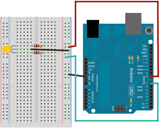
Making The Circuit
This is the basic circuit to have a go with a single one of these LEDs,
Programming The Arduino
The following sketch will make the LED go red, green, yellowy-orange and then off, with a half-second delay between each change. It's useful to check that you are sure which pin is red and green.
const int red = 7;

const int green = 8;


void setup()

{

  pinMode(red, OUTPUT);

  pinMode(green, OUTPUT);

}


void loop()

{

  digitalWrite(red, HIGH);

  delay(500);

  digitalWrite(red, LOW);

  delay(500);

  digitalWrite(green, HIGH);

  delay(500);

  digitalWrite(green, LOW);

  delay(500);

  digitalWrite(green, HIGH);

  digitalWrite(red, HIGH);

  delay(500);

  digitalWrite(green, LOW);

  digitalWrite(red, LOW);

  delay(500);

}
Challenges
The three colours of these LEDs are a nice match for traffic lights. With 4 of them, some switches, and a paper drawing of a road, you can make a decent simulation of a pedestrian crossing. The key to that is timing which you should work out well before hitting the Arduino. There's a lot to do and synchronise. If you can manage that with efficient, tidy code, you are doing very well.
Alternative Wiring
The following circuit demonstrates the way to use this LED with a single pin.
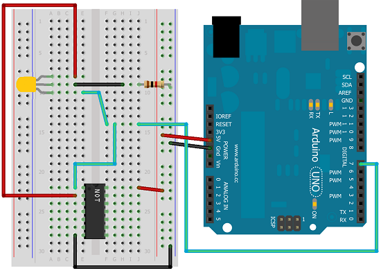
The integrated chip is a NOT gate, the 74HCT04. In fact, the IC has 6 NOT gates. The output from pin 7 goes into one of the anodes and as well as into the NOT gate. The output from the NOT gate (the inverse of its input) is fed into the other anode of the LED. Whether the pin is HIGH or LOW, one of the anodes will be receiving HIGH whilst the other receives LOW. That eliminates one of the resistors in our circuit since we can only light one LED at a time. That's two of the states we can put the component into (red LED on and green LED on). To have both LEDs on we need to alternate very quickly. Finally, if we set the pin to be an INPUT, both of the LEDs go out. The following sketch cycles through those 4 states.
const int bicolour = 7;


void setup()

{

  pinMode(bicolour, OUTPUT);

}


void loop()

{

  pinMode(bicolour, OUTPUT);

  //red

  digitalWrite(bicolour, HIGH);

  delay(500);

  //green

  digitalWrite(bicolour, LOW);

  delay(500);

  //mixed

for (int i = 0;i<250;i++)

{

  digitalWrite(bicolour, HIGH);

  delay(1);

  //green

  digitalWrite(bicolour, LOW);

  delay(1);


}

pinMode(bicolour, INPUT);

delay(500);


}
Further Challenges
LEDs are basically indicators. If an LED can be lit or not lit, you have 2 states - this would mean one of two things to the person looking at the circuit in use. With bi-colour LEDs, there are 4 states. Four things can be indicated with a single component. That for example, makes it easy to indicate who wins in a 2 player game or whether to start or stop doing something. A game of noughts and crosses could be made using a couple of the NOT ICs, 9 or 10 bicolour LEDs and some switches. A nice light show from half a dozen of these would look good too.