Other
Arduino - LED Projects
Arduino - Buzzer Projects
Arduino - Midi Projects
Arduino - Microview
Arduino - Other Projects
Arduino - Visual Basic.NET
Arduino - Tim's Projects
Arduino - Links
![]()


Rotary Encoder
Introduction
A rotary encoder has a knob to rotate a little bit like a rotary potentiometer. One big difference is that the knob can be rotated continuously. There are two main types of output from a rotary encoder, Gray Code and Quadrature. Both are binary codes to represent data from the encoder. Depending on the type of encoding, a rotary encoder's output could indicate the absolute position of the knob or the amount and direction of a rotation of the encoder by the user.
In this project, a Sparkfun red/green LED rotary encoder is used. The encoder (shown below) has a bi-colour LED and a pushbutton built into the knob.
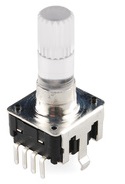
There is an RGB version of the component at a slightly higher price. Both rotary encoders have their switch and LED pins grouped on one side, with their encoding pins on the other. There are also some support pins like you find on buttons. This makes the encoder a little difficult to use with a breadboard. It's easier to solder one to some perfboard for prototyping.
You Will Need
- 2 x 330 Ohm Resistors
- Sparkfun Illuminated Red/Green Rotary Encoder
- Jumper Wires
Making The Circuit - LED & Switch
The first step is the easier job of making sure we can receive data from the switch and control the LED.
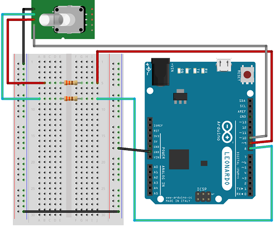
You'll notice that there is no 10K pull-up resistor shown on the breadboard. The Arduino has built-in pull-up resistors that can be turned on in the sketch. This makes the wiring a little easier.
Programming The Arduino - LED & Switch
This first sketch is used just to test that the LEDs are wired correctly and that we can make the Arduino respond to the switch being pressed. When you upload it, the LED should glow red when pressed and green at other times.
const int green = 8;

const int red = 9;

const int button = 10;


void setup()

{

  pinMode(red, OUTPUT);

  pinMode(green, OUTPUT);

  pinMode(button, INPUT);

 digitalWrite(button, HIGH);

}


void loop()

{

  if (digitalRead(button)==LOW)

  {

    digitalWrite(red, LOW);

    digitalWrite(green, HIGH);

  }

  else

  {

    digitalWrite(red, HIGH);

    digitalWrite(green, LOW);

  }

}
Challenges
Even at this stage, there is a lot of mucking around that can be done. Essentially, you have a bi-colour LED of the 3-pin variety allowing you to do some of the things described in those pages. You can, for example, achieve the same effect as the sketch if you use a NOT gate and a single pin on the Arduino for the two LEDs.
A more useful way to program the LED would be to use the red and green LEDs as indicators for enabled and disabled. Imagine a device where you have to press the knob before turning it creates an effect on the device. In that case, we would want the button pressing to toggle the colours on the LED.
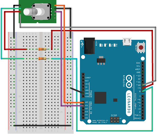
Making The Circuit - Encoder
The LED and switch are shown connected in this diagram. They are not used in the sketch though.
Programming The Arduino - Encoder
The sketch here is taken from the this tutorial. Further explanation can be found on that page.
#define encA 14

#define encB 15

#define encPort PINC


void setup()

{

  pinMode(encA, INPUT);

  digitalWrite(encA, HIGH);

  pinMode(encB, INPUT);

  digitalWrite(encB, HIGH);

  Serial.begin (115200);

  Serial.println("Rotary Encoder Example");

}


void loop()

{

  static uint8_t counter = 0;

  int8_t tmpdata;

  tmpdata = read_encoder();

  if( tmpdata ) {

    Serial.print("Counter: ");

    Serial.println(counter, DEC);

    counter += tmpdata;

  }

}


int8_t read_encoder()

{

  static int8_t enc_states[] = {0,-1,1,0,1,0,0,-1,-1,0,0,1,0,1,-1,0};

  static uint8_t old_AB = 0;

  old_AB <<= 2;

  old_AB |= ( encPort & 0x03 );

  return ( enc_states[( old_AB & 0x0f )]);

}
You need to open up the Serial Monitor and set its baud rate to 115200 to see the effect of turning the knob. There is a little bit of jitter on the values - usually by 1. Given a counter of 255, that is enough precision for most applications which might scale down the actual value of the counter.
Challenges
Connect this up to use as a brightness adjustor for an LED. There is a similar project on this site using a trimpot to control the fading of the LED. Notice that the counter goes from 0 to 255 if you move turn anti-clockwise. You could make the counter stop at the upper and lower boundaries. Look a the section in the loop where the value of tmpdata is being examined. This variable will hold the values -1, 0, 1. If tmpdata is -1, the knob was turned anti-clockwise. If it is 1, then it was turned clockwise. A 0 means no change. Change the if statement to process the counter differently to ensure that the light can never go from off to full brightness in one turn.
It would be good to set up a rotary potentiometer alongside a rotary encoder and test the two components together as inputs for a variety of applications.